16 17
Operation
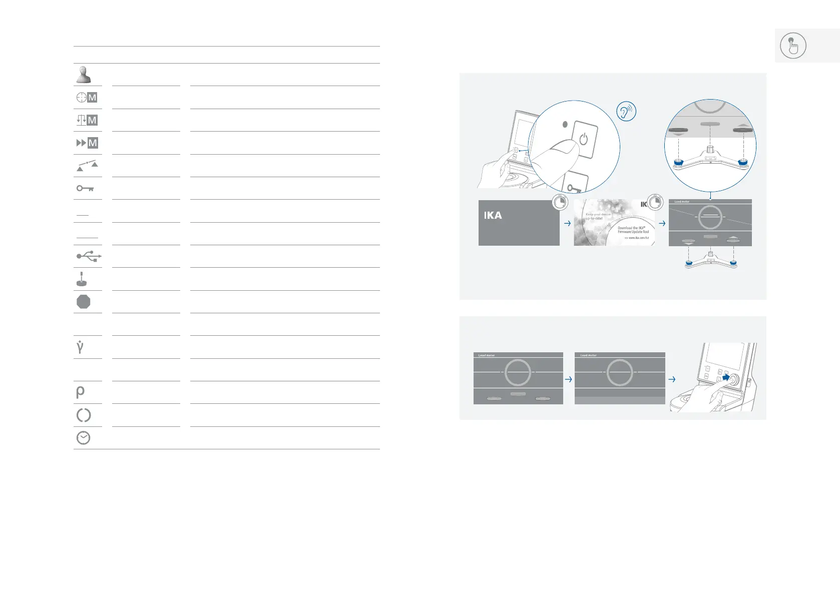
/// Switching on and levelling:
Note: The short horizontal white line inside the circle is moving vertically and it represents the
rotation around the Y-axis� When it matches the white line, the device will be in balance with
the Y-axis, then the line color will turn from white to green�
The three buttons represent the three stand levelers� The arrows show in which direction they
have to be adjusted (green = up; red = down)�
The other two moving lines:
The red angular line pivoting around the center of the circle represents the rotation of the
device around the X-axis� When the line is horizontal (matching the white line), the device will
be in balance with the X-axis, and then the line color will turn from red to green�
Rotavisc
xx-vi
Version x.x.xxx/x.xx
ON
1
2
/// Explanation of symbols on the working screen:
Symbol Designation Function
Profile symbol Indicate the selected profile�
Accurate mode symbol Indicate the accurate mode is selected�
Balanced mode symbol Indicate the balanced mode is selected�
Fast mode smbol Indicate the fast mode is selected�
Level broken symbol Indicate the device is no longer level�
Lock symbol Indicate the buttons and control knob is locked�
PC
PC control symbol Indicate the device is controlled by a PC�
RMP
Ramp control symbol Indicate the device is in ramp control mode�
USB connection symbol Indicate the device is communicating via USB
Spindle symbol Indicate the selected spindle
Stop
Stop condition symbol Indicate the stop condition
τ
Shear stress symbol Indicate the measured shear stress of the media�
Shear rate symbol Indicate the measured shear rate of the media�
T
Temperature symbol Indicate the measured temperature of the media�
Density symbol Indicate the density of the media�
Running symbol Indicate the device is in running status�
Timer symbol
Indicate the timer function is activated�