7
4. Input Signal Connection
Connect the input signals in the following way.
4.1 NTSC/PAL Analog Video : Connected to the Video input.
4.2 NTSC/PAL Analog S-Video: : Connected to the S-Video input.
4.3 RGB or YPbPr Analog signals (BNC connector)
G/Y: Connected to Component G/Y input.
B/Pb: Connected to Component B/Pb input.
R/Pr: Connected to Component R/Pr input.
Sync: Connected to Component Sync input.
4.4 PC Analog signal : Connected to PC input. (15P D-SUB connector)
4.5 PC Digital signal : Connected to DVI input.
4.6 NTSC/PAL/HD Digital Video : Connected to SDI input.
Note: Various signal inputs (Video, S-Video and RGB) are automatically terminated. Be
sure to connect them to the input side because otherwise malfunction may occur.
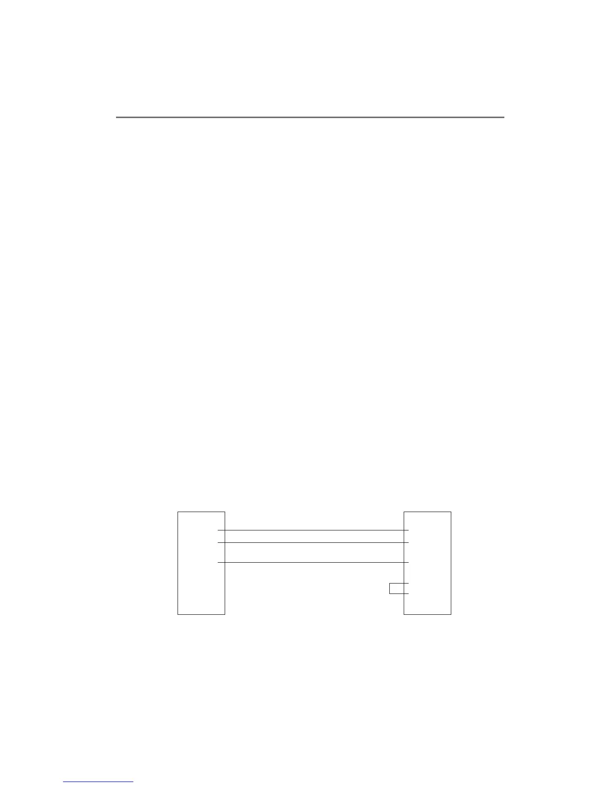
1.
2.TXD
3.RXD
4.
5.GND
6.
7.
8.
9.
1.
2.RXD
3.TXD
4.
5.GND
6.
7.RTS
8.CTS
9.
D-SUB 9 pin connector on
LCD Monitor back
External PC/D-SUB
9 pin Connector
Note: At the PC, Pins 7 and 8
must be loop-connected.
Do not connect anything to pins 1, 4, 6,
7, 8, or 9 on the monitor side (or else, a
malfunction of the monitor may occur).
Be sure to use a shielded cable for a remote signal cable. Please contact the sales
agent where you purchased the product for details.
4-7. Remote Connection :
Remote control is possible with a remote control signal feed.
 Loading...


