User’s Manual REVEXplus, REVEXplus USB
Copyright © 2006–2019 ILLKO, s.r.o.
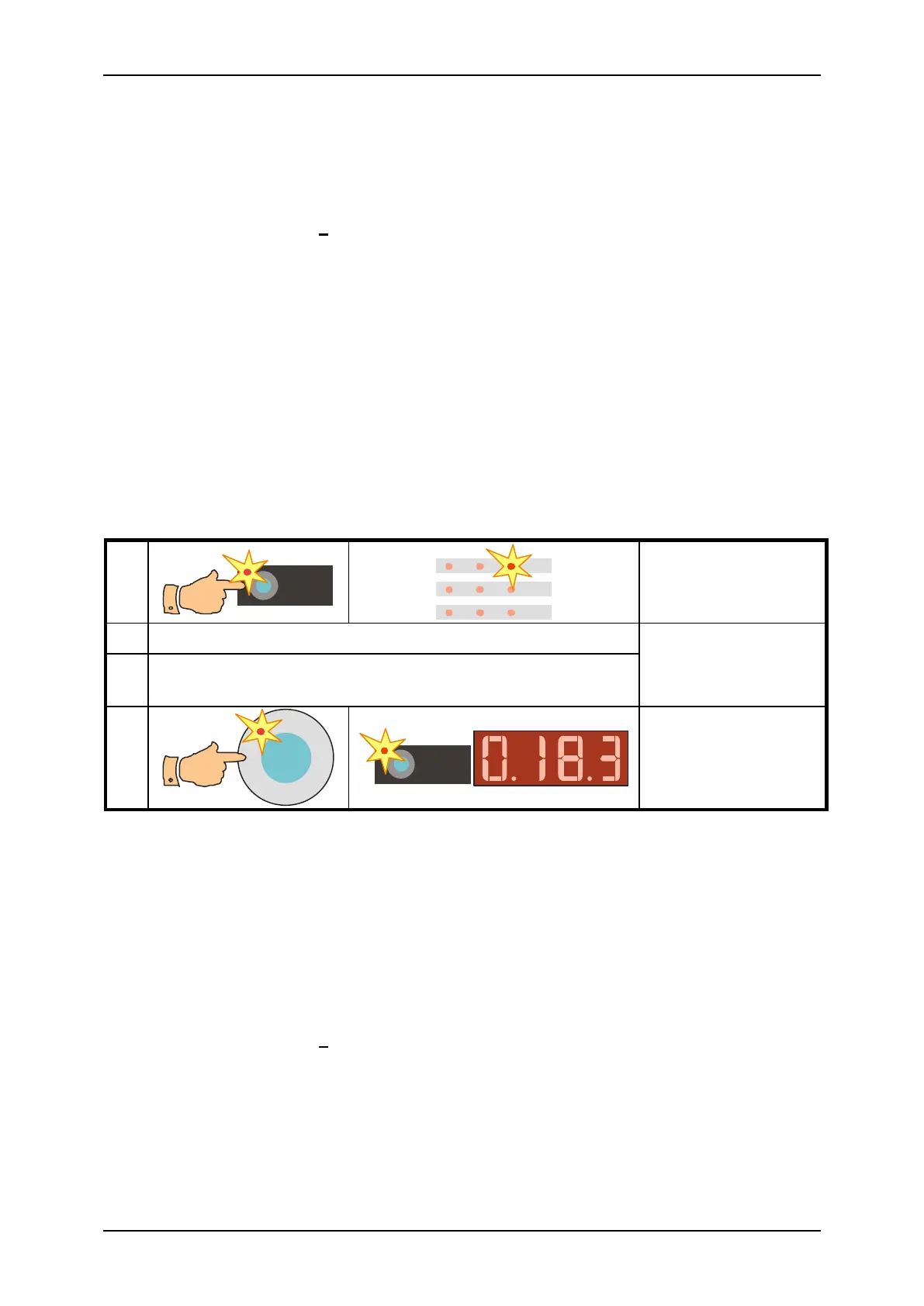
• Pres the R
PE
key and release it. Symbol „- -“ is displayed and indicators (R
PE
) and
() light up.
• Connect test lead P2011 with test tip P3011 to the R
PE
terminal.
• Connect test tip of the test lead either to the PE terminal or press it against the ground
pin of the test socket 1. If you use two test leads (which are connected to the PE
terminal and the R
PE
terminal) then make short-circuit of their test tips.
• Press the CAL key and release it. Now the indicators (CAL), (R
PE
) and () shine.
• Press the START key and release it. Test lead resistance is shortly displayed, then the
(CAL) indicator turns off and „0.000“ is displayed. Test lead resistance compensation is
finished.
The compensation is effective for test lead resistance < 2 .
If test lead resistance is ≥ 2 and compensation procedure is carried out, compensation is
cancelled and all following displayed results are a sum of earth bond + test lead resistance.
If compensation is active (it means that test lead resistance < 2 was memorized) then the
(CAL) indicator lights up during R
PE
measurements.
4.2.2. Earth bond measurement
Press the test tip connected to the R
PE
terminal
against exposed conductive part of tested appliance
Fig. 4 – Earth bond measurement
Step 1 - preparation for measurement
• Select the R
PE
function: pres the R
PE
key and release it. Symbol „- -“ is displayed and
indicators (R
PE
) and () light up.
• Connect test lead P2011 with test tip P3011 to the R
PE
terminal.
• If test lead compensation was not carried out yet, compensate it now – see details in
chapter 4.2.1.
• Connect tested appliance:
- One-phase appliance with movable power supply cord – plug in its mains plug
to test socket 1.
- Three-phase appliance with movable power supply cord – connect PE pin of its
plug to the instrument’s PE terminal by means of optional test lead P2012 +
crocodile clip P4012.
- Hard-wired appliance – firstly disconnect appliance from mains! Connect its
point of PE connection to the instrument’s PE terminal by means of optional
test lead P2012 + crocodile clip P4012.