- One-phase appliance with movable power supply cord – plug in its mains plug
to test socket 1.
- Three-phase appliance with movable power supply cord – connect PE pin of its
plug to the instrument’s PE terminal by means of optional test lead P2012 +
crocodile clip P4012. Then connect remaining current-carrying conductors by
means of test lead P2011 + test tip P3011 to the instrument’s R
ISO
+ I
SUB
terminal (placed on rear panel).
- Hard-wired appliance – firstly disconnect appliance from mains! Connect its
point of PE connection to the instrument’s PE terminal by means of optional
test lead P2012 + crocodile clip P4012. Then connect remaining current-
carrying conductors by means of test lead P2011 + test tip P3011 to the
instrument’s R
ISO
+ I
SUB
terminal (placed on rear panel).
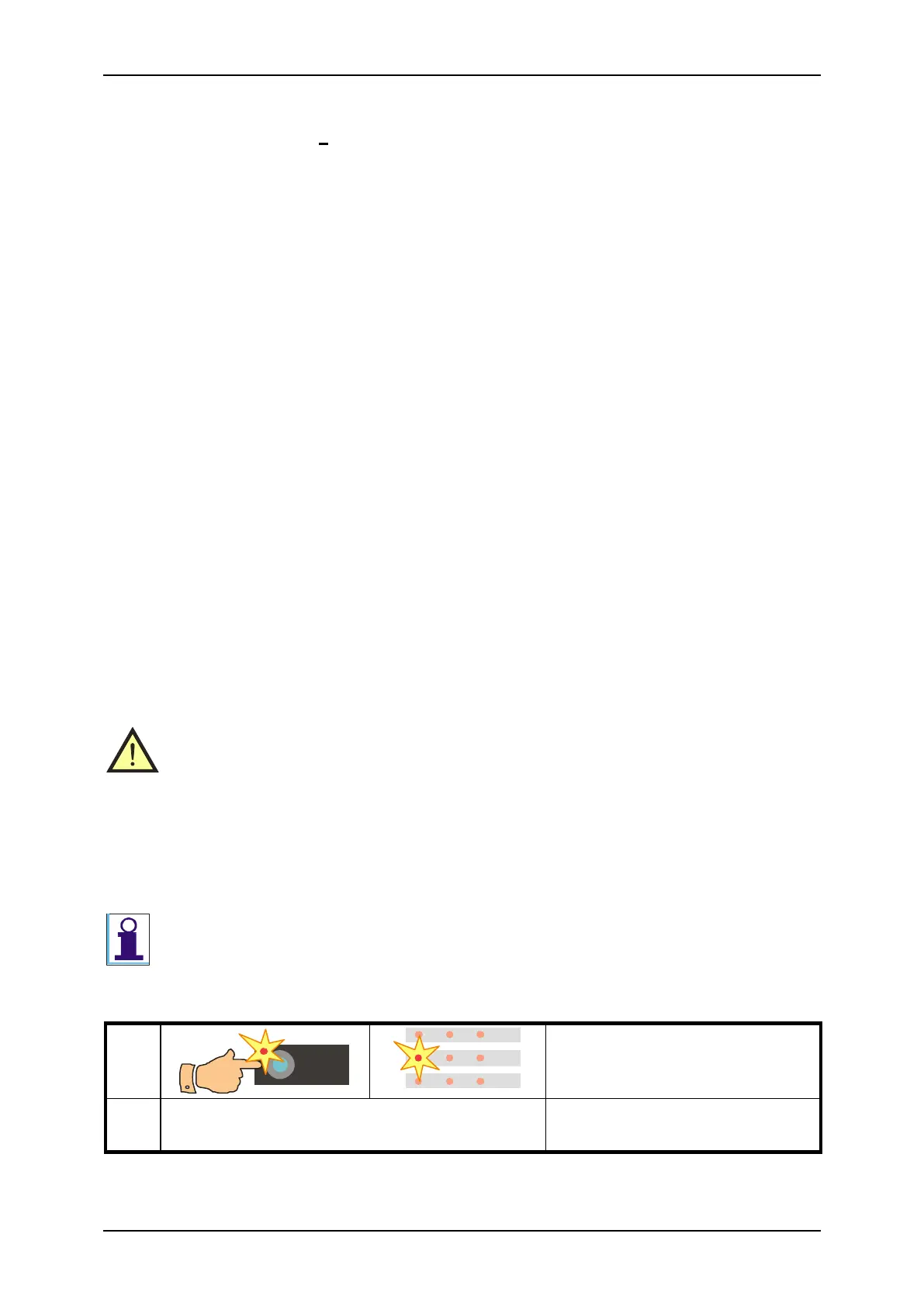
Step 2 - measurement
• Switch on tested appliance’s mains switch.
• Press the START key; measurement starts to run (see chapter 4.1. for measurement
control details). Measurement is indicated by the (START) indicator. It is
recommended to hold the START key pressed 5-10 s (or even longer if displayed
result is not stabilized) - the influence of tested appliance’s internal capacitance can be
eliminated by this method.
• After finishing of measurement (the (START) indicator turns off) the last measured
value of insulation resistance is displayed. At the same time either indicator
(M) or (k) lights up and so the unit of measured insulation resistance is determined.
If only „1“ is displayed (see chapter 5.1 for details) it means that measured insulation
resistance is higher than maximal value which can be measured by the REVEXplus.
4.4. Substitute leakage current - I
SUB
• Make sure tested appliance is deenergized – its mains voltage must be
disconnected before starting of measurement!
• Firstly earth bond resistance (chapter 4.2.) must be tested; it is recommended
to test insulation resistance, too (chapter 4.3.). Then you can execute
substitute leakage current measurement!
• Do not touch exposed conductive parts of tested appliance while measurement
is in progress – RISK OF ELECTRC SHOCK! Measurement in progress is
indicated by the (START) indicator.