User’s Manual REVEXplus, REVEXplus USB
Copyright © 2006–2019 ILLKO, s.r.o.
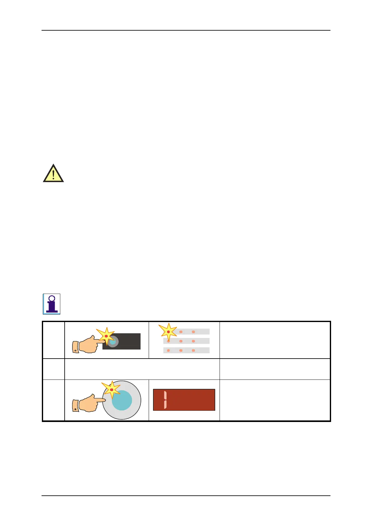
Step 2 - measurement
• Press test tip against exposed conductive part of tested appliance.
• Press the START key; measurement starts to run (see chapter 4.1. for measurement
control details). Measurement is indicated by the (START) indicator. If the (CAL)
indicator lights on during measurement, it means that test lead resistance is
compensated (see chapter 4.2.1. for details).
• After finishing of measurement (the (START) indicator turns off) the lowest measured
value of earth bond resistance is displayed. If only „1“ is displayed (see chapter 5.1 for
details) it means that measured earth bond resistance is higher than maximal value
which can be measured by the REVEXplus.
4.3. Insulation resistance - R
ISO
• Make sure tested appliance is deenergized – its mains voltage must be
disconnected before starting of measurement!
• Do not touch exposed conductive parts of tested appliance while measurement
is in progress – RISK OF ELECTRC SHOCK! Measurement in progress is
indicated by the (START) indicator.
• Do not disconnect test leads while measurement is in progress or immediately
after finishing the measurement. Capacitive component of tested appliance can
be charged to voltage up to 750 V; after the key START is released, this
voltage is automatically discharged! If the capacitive component would be so
extraordinary high that the discharging circuitry in the REVEXplus would not
be able to discharge it to voltage < 50 V, the message „Prot“ would be
displayed. Tested appliance must be disconnected from the instrument in this
case and its capacitance must be discharged by another alternative safe
method.
In case that external voltage is present on tested appliance, measurement will not be
carried out. Indicator (PROTECT) turns on and message „Prot“ is displayed.
Connect tested appliance; its mains
switch must be switched on
Fig. 5 – Insulation resistance measurement
Step 1 - preparation for measurement
• Select the R
ISO
function: pres the R
ISO
key and release it. Symbol „- -“ is displayed
and indicators (R
ISO
) and (M) light up.
• Connect tested appliance: