INSTALLATION PROCEDURES
3-5
When the dryer is operating, it draws in room air, heats it, passes this air through the basket
(tumbler), and exhausts it out of the building. Therefore, the room air must be continually
replenished from the outdoors. If the make – up air is inadequate, drying time and drying efficiency
will be adversely affected. Ignition problems and sail switch “fluttering” problems may result, as
well as premature motor failure from overheating.
Air supply (make – up air) must be given careful consideration to assure proper
performance of each dryer. An unrestricted source of air is necessary for each dryer. An air flow of
2,150 cfm (cubic feet per minute) must be supplied to each gas dryer and electric dryer with a
72 Kw oven, 2,500 cfm to each electric dryer with an 80 Kw oven, and 2,750 cfm for each steam
dryer. As a general rule, an unrestricted air entrance from the outdoors (atmosphere) of a minimum
of three (3) square feet is required for each gas dryer and 72 Kw electric dryer and a minimum of
five (5) square feet for each steam dryer and 80 Kw electric dryer.
To compensate for the use of registers or louvers used over the openings, this make – up air
area must be increased by approximately thirty – three (33) percent. Make – up air openings should
not be located in an area directly near where exhaust vents exit the building.
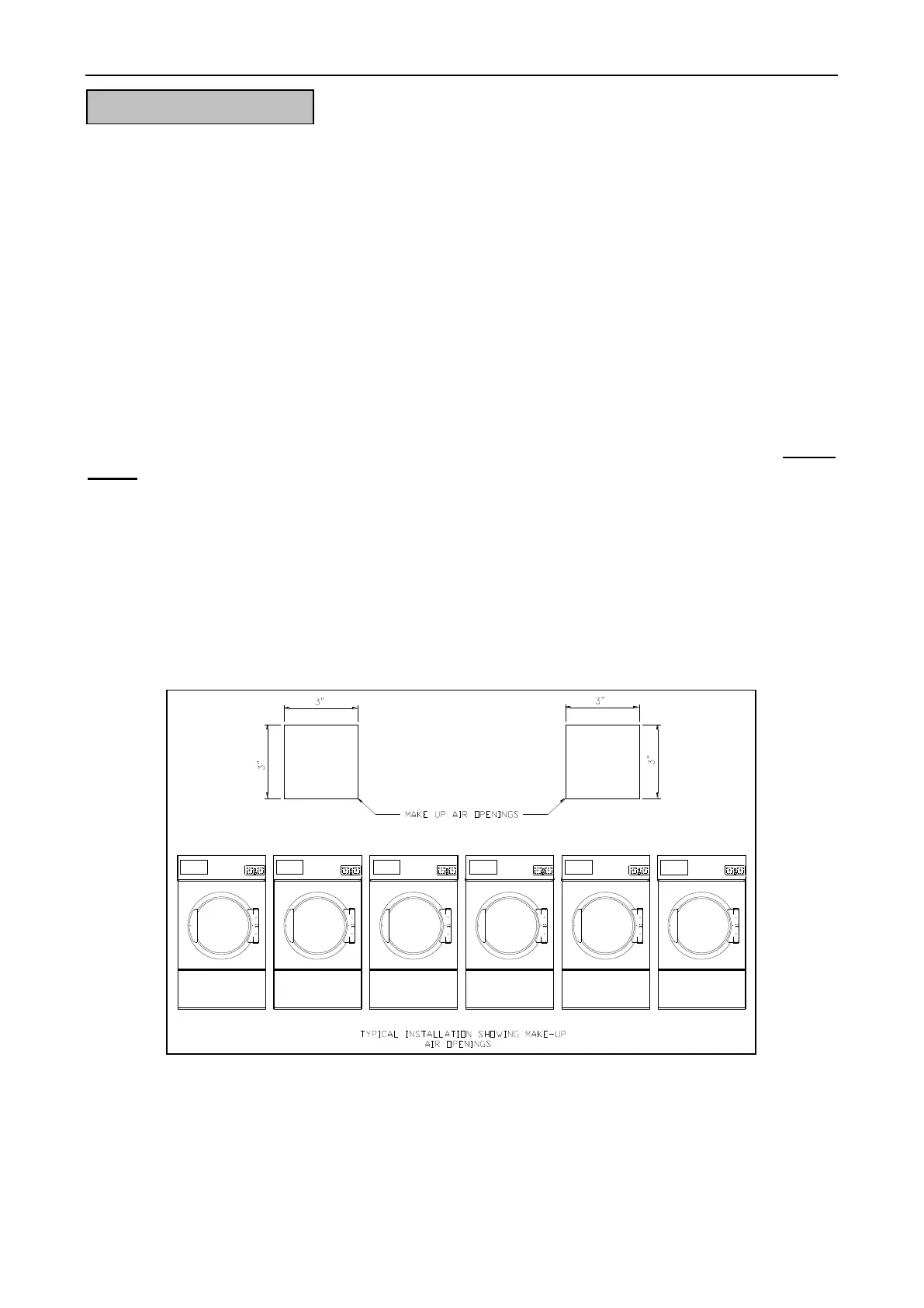
It is not necessary to have a separate make – up air opening for each dryer. Common make –
up air openings are acceptable. However, they must be set up in such a manner that the make – up
air is distributed equally to all the dryers.
EXAMPLE: For a bank of six (6) gas dryers, two (2) openings measuring 3 feet by 3 feet (18
square feet) is acceptable.
Allowances must be made for remote or constricting passageways or where dryers are
located at excessive altitudes or predominantly low pressure areas.
Figure.3-5 Fresh Air Supply