INSTALLATION PROCEDURES
3-18
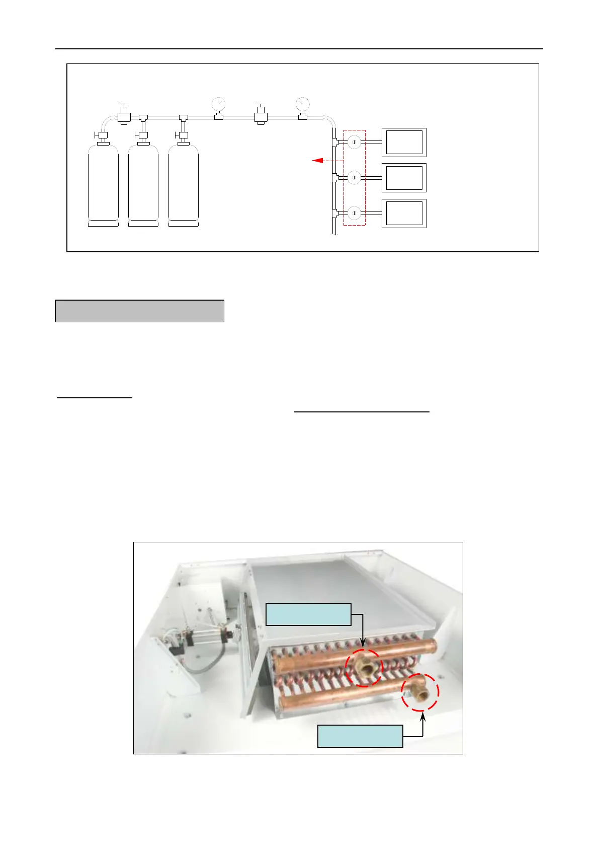
Figure.3-12 Typical of Gas Installation
It is your responsibility to have all steam plumbing connections made by a qualified
professional to assure that the installation is adequate and conforms to local and state regulations or
codes.
IMPORTANT: Failure to comply with the requirements stipulated in this manual can result in
component failure which will. VOID THE WARRANTY.
NOTE: The DE – 100 lb. is manufactured with a pneumatic (piston) damper system
which requires an external supply of clean, dry, regulated air (80 Psi ± 10 Psi).
Refer to Steam Damper Air System Connections, Section H, item 3.
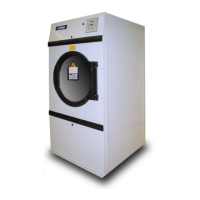
1. Steam Requirements. High Pressure
a. Inlet --- 1 – 1/4 – inch supply line connection – Qty. one (1) at top manifold.
b. Return --- 1/2 – inch return line connection – Qty. one (1) at bottom manifold.
Figure.3-13 Typical of Steam Installation
MAIN GAS SUPPLY TANKS
HIGH PRESSURE 0-300PSI
PRESSURE
RELIEF VALVE
HIGH PRESSURE
GAUGE 0-300PSI
PRESSURE GAUGE 0-60PSI
MEASURING 7PSI (0.48BAR)
HIGH PRESSURE
REGULATOR
GAS SUPPLY LINE 7PSI
LOW PRESSURE
SECOND STAGE
GAS REGULATOR
MAX INLET PRESSURE
10PSI (0.69BAR)
OUTLET PRESSURE
12-14 INCHES WC. (LPG)
4.5-14 INCHES WC. (NG)
GAS DRYER MACHINE
WITH GAS VALVE MAX INLET
PRESSURE 0.5PSI BUT IF USE
SECOND STAGE REGULATOR
WITH 11 INCHER WC. 0.41PSI (LPG)
4 INCHES WC.0.145 PSI (NG)