INSTALLATION PROCEDURES
3-14
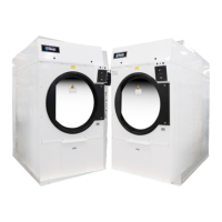
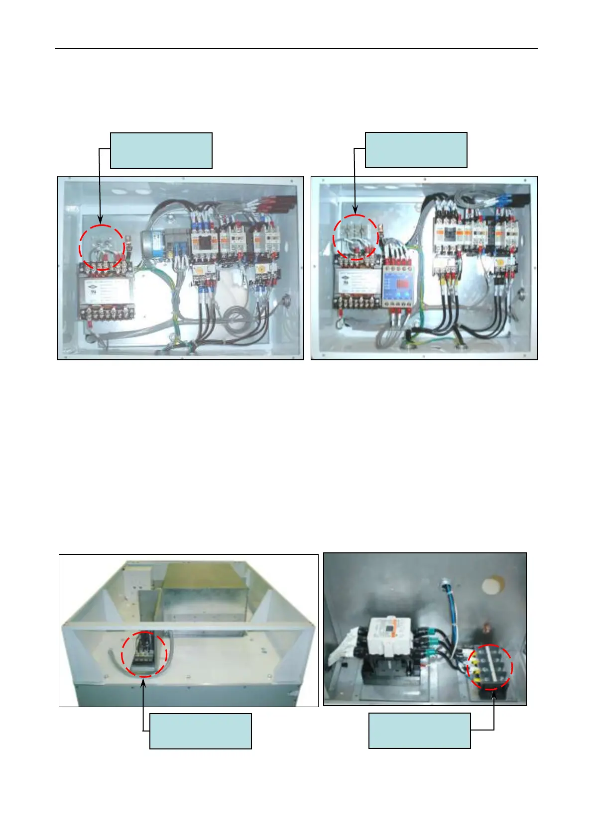
a. Gas Model and Steam Model Dryer
These electrical connections are made at the terminal block located in the electric service /
relay box at the rear, upper left hand corner of the dryer. To gain access into this service box, the
service cover (upper back guard) must be removed.
Timer Type Microprocessor Type
Figure.3-10 Electric Power Connector, Gas and Steam Model
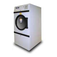
b. Electric Model Dryer
For electric model dryers made to operate at 208 VAC, 230 VAC, or 240 VAC, the
electrical input connection is made into the terminal block located at the upper rear of the dryer. For
electric model dryers made to operate at 380 VAC, 416 VAC, 440 VAC, or 480 VAC, the electrical
input connection is made to the oven relay located at the upper rear of the dryer. Input connection
wiring must be sized properly to handle the dryer's current draw. This information is printed on the
dryer's data label which is affixed to the rear, upper right hand comer of the dryer.
Figure.3-11 Electric Power Connector, Electric Heater Model
Power connector
(R, S, T)
Power connector
(R, S, T)
Power connector
(R, S, T)
Power connector
(R, S, T)