INSTALLATION PROCEDURES
3-20
g. The supply and return lines should be insulated. This will save energy and provide for the
safety of the operator and maintenance personnel.
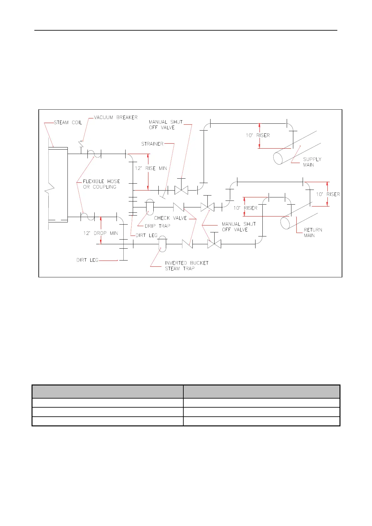
h. Water pockets in the supply line, caused by low points, will provide wet steam to the coil
possibly causing coil damage. All horizontal runs of steam supply piping should be
pitched 1/4 – inch for every one (1) foot back towards the steam supply header causing
any condensate in the line to drain to the header. Install a bypass trap in any low point to
eliminate wet steam.
Figure.3-15 Typical of Steam System
3. Steam Damper Air System Connections
The Dryer – 100 lb. is manufactured with a pneumatic (piston) damper system which
requires an external supply of compressed air. The air connection is made to the steam damper
solenoid valve which is located at the rear inner top area of the dryer just above the electric service
relay box
a. Air Requirements
Table 3-5 Steam Damper Air System Connections
b. Air Connection
Air connection to system 8 mm.
No air regulation or filtration is provided with the dryer. External regulation / filtration of
80 Psi must be provided. It is suggested that a regulator / filter gauge arrangement be added to the