IMI Sensors: A PCB Piezotronics Div 699A07 User Manual
MAN-0192 rev A Page 15 of 39 800-959-4464
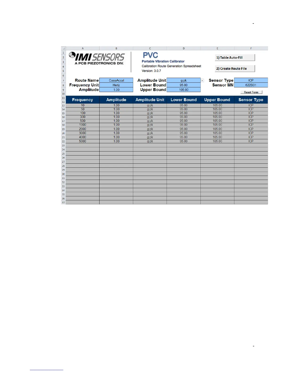
Example Accelerometer Test (Route)
An example of a 10-point accelerometer test, created in the Report Generation
Workbook, is shown above. Some helpful notes…
• When run, this test will shake the accelerometer at 1g pk at all points. If the shaker
cannot generate 1g pk it will output the maximum vibration possible given the
sensor’s weight and test speed. The shaker will not allow user to program points
that can damage the shaker.
• The test will begin at 10 Hz and end at 5000 Hz, with test points at 50,100, 300,
500, 1000, 2000, 3000 and 4000 Hz as well.
• If the sensor under test’s sensitivity is above 105 mV/g or below 95 mV/g the
699A07 will alert the user that test point failed.
• The file name will be CaseAccel_Route.pvc, when uploading to the 699A07 one
would choose this file.
• ICP® power is active for all test points. If this test were applied to a self-powered
sensor data would be invalid. One would select “Voltage” for a self-powered sensor
such as a moving coil velocity transducer.
 Loading...