IMI Sensors: A PCB Piezotronics Div 699A07 User Manual
MAN-0192 rev A Page 16 of 39 800-959-4464
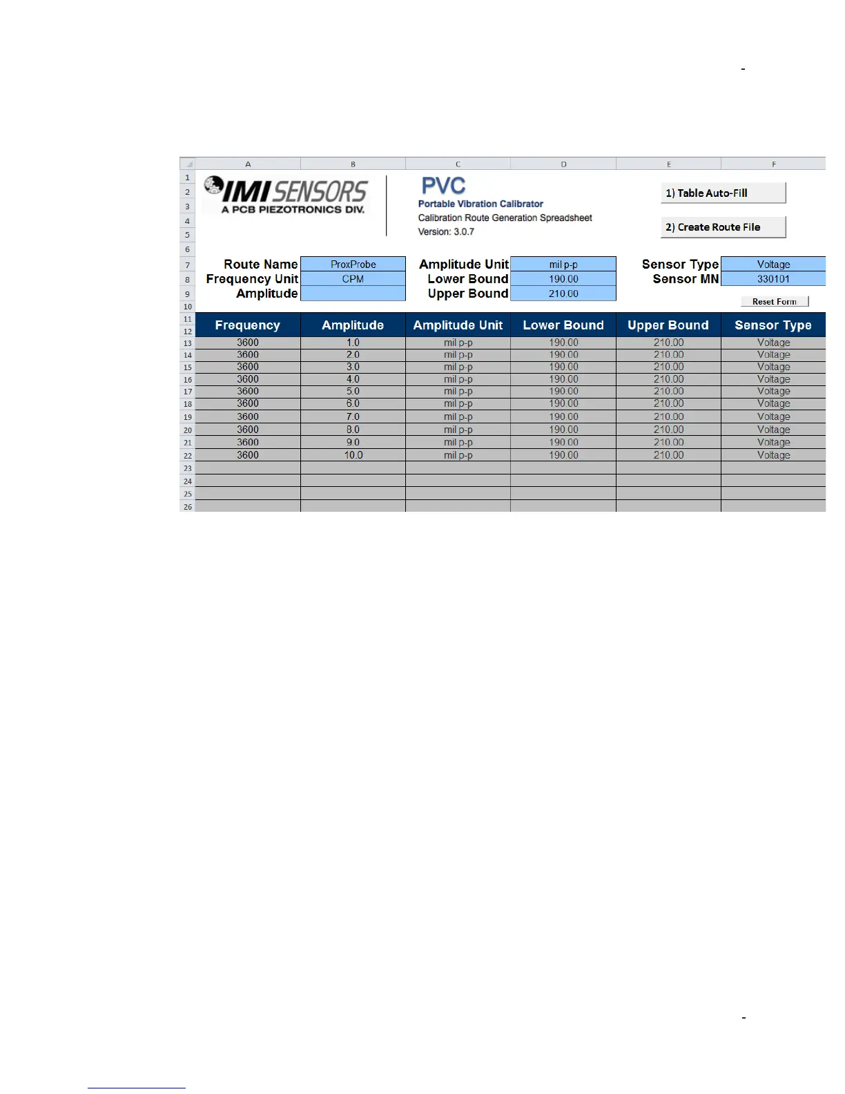
Example Proximity Probe Test (Route)
An example of a 10-point proximity probe test, created in the Report Generation
Workbook, is shown above. Some helpful notes…
• This test will simulate vibration at 3600 CPM for all test points.
• This is a linearity test. Vibration will start at 1.0 mils p-p and escalate to 10.0 mils p-
p. The sensor will be evaluated every 1.0 mils.
• The test is designed for a 200 mV/mil proximity probe with 5% tolerance. Thus
sensitivity of 190-210 mV/mil passes calibration. If outside those values the 699A07
will indicate the test point has failed.
• The sensor type is voltage. This means ICP® power is turned off. The proximity
probe is being powered by its probe driver. To run this test the technician must
connect the output of the probe drive to “Test Sensor In” on the 699A07.
• The name of the file will be ProxProbe_Route.pvc.
• The model number 330101 will print on each test report created using this route. It
can be modified on the certificate if desired to add thread lengths, cable length, etc.
Loading & Activating a Calibration Test (Route)
With the calibration test saved as a .pvc file to the Calibration_Route folder on the
USB and the USB inserted into the port on the 699A07 the following instructions
detail how to upload to model 699A07 and activate:
1. Press the FREQUENCY dial to enter “Calibration Options” menu, rotate to highlight
TEST SETTINGS and press again to enter “Test Settings” menu.
2. Use FREQUENCY dial to highlight and click selection next to “Cal Route:”. Selection
will be “Off” or “Active” depending upon previous status. When clicked user will enter
into “Route Option” menu.
a. If display indicates “Cal Route: n/a” the 600A31 firmware has not been
purchased. Contact IMI Sensors to add this firmware to the 699A07.
3. Use FREQUENCY dial to highlight and click on LOAD FILE FROM USB
 Loading...