TECHNICIAN
INSTALLER
USER
31
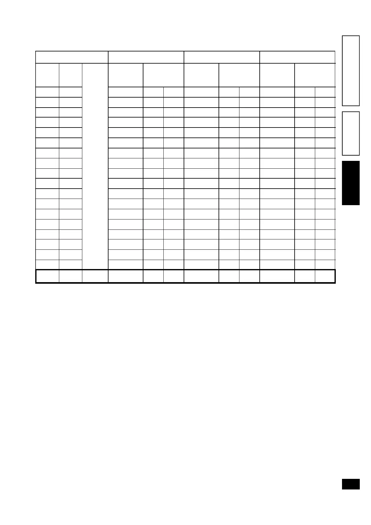
3.15 Eolo 27 Maior @ variable heating power.
N.W.: Pressure values specified in the table indicate
the difference of pressure values between the gas
valve outlet and the combustion chamber. Adjust-
ments are therefore carried out with the differential
pressure gauge ( “U” or digital type) with the sensors
inserted in the test pressure outlet of the modulating
adjustable gas valve and on the sealed chamber posi-
tive pressure test outlet . Power data specified in the
table refer to a 0,5 metre intake/exhaust pipe. Gas
flow rates refer to heat power below temperature of
15°C and at a pressure of 1013 mbar. Burner pres-
sure values refer to use of gas at 15°C.
METURAL GAS (G20) BUTANE (G30) PROPANE (G31)
HEATING
POWER
(kcal/h)
HEATING
POWER
(kW)
BURNER GAS
FLOW RATE
(m
3
/h)
BURNER NOZZLE
PRESSURE
(mbar) (mmw.g.)
BURNER GAS
FLOW RATE
(kg/h)
BURNER NOZZLE
PRESSURE
(mbar) (mmw.g.)
BURNER GAS
FLOW RATE
(kg/h)
BURNER NOZZLE
PRESSURE
(mbar) (mmw.g.)
27000 31,4 3,63 12,01 122 2,71 27,02 276 2,67 35,02 357
26000 30,2 3,50 11,16 114 2,61 25,09 256 2,57 32,60 333
25000 29,1 3,37 10,35 106 2,51 23,26 237 2,47 30,28 309
24000 27,9 3,24 9,57 98 2,42 21,50 219 2,38 28,06 286
23000 26,7 3,12 8,83 90 2,32 19,82 202 2,29 25,94 265
22000 25,6 2,99 8,12 83 2,23 18,22 186 2,19 23,91 244
21000 24,4 2,86 7,44 76 2,13 16,70 170 2,10 21,97 224
20000 23,3 2,74 6,80 69 2,04 15,24 155 2,01 20,11 205
19000 22,1 2,61 6,18 63 1,94 13,85 141 1,92 18,34 187
18000 20,9 2,48 5,59 57 1,85 12,53 128 1,82 16,64 170
17000 19,8 2,36 5,03 51 1,76 11,27 115 1,73 15,03 153
16000 18,6 2,23 4,49 46 1,66 10,07 103 1,64 13,49 138
15000 17,4 2,11 3,98 41 1,57 8,94 91 1,54 12,02 123
14000 16,3 1,98 3,50 36 1,47 7,87 80 1,45 10,63 108
13000 15,1 1,85 3,04 31 1,38 6,86 70 1,36 9,31 95
12000 14,0 1,72 2,61 27 1,28 5,91 60 1,26 8,06 82
11000 12,8 1,59 2,20 22 1,18 5,02 51 1,17 6,89 70
10750 12,5 1,56 2,10 21 1,16 4,80 49 1,14 6,61 67
7663 8,9
Doestic
Water
1,16 1,10 11 0,87 2,80 29 0,85 3,60 37