TECHNICIAN
INSTALLER
USER
15
on the female section (with lip seal) to the end stop
on the previously installed to ensure sealing effi-
ciency of the couplings.
• Insulation of separator terminal. In the event of
problems of condensation of flues inside the ex-
haust pipes or on the outside surface of the intake
pipes, on request Immergas supplies insulated in-
take and exhaust pipes. Insulation may be neces-
sary on exhaust pipes due to excessive drops in
temperature of flues during conveyance from the
boiler and on the intake pipes as air on input (cold)
may cause the external pipe temperature lower
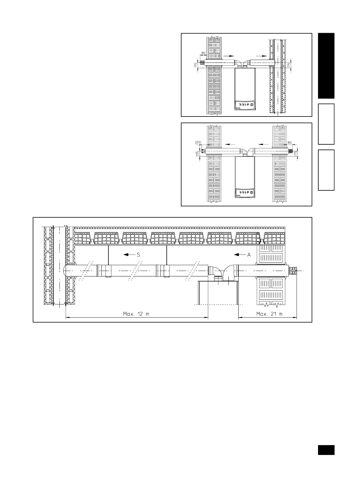
than the dew point of the ambient air. The figures
below illustrate different applications of insulated
pipes.
Insulated pipes comprise an internal Ø 80 concen-
tric pipe and a Ø 125 external pipe with static air
jacket. Technically it is not possible to start with
both Ø 80 elbows insulated as clearances will not
allow this type of installation. However an insulated
elbow can be used by selecting either the intake
or exhaust pipe. If an insulated intake pipe is used,
the flange must be inserted to the end stop on the
flue extraction flange to ensure that the height of
the two intake and exhaust outlets is aligned.
• Temperature loss in insulated ducting. To avoid the
problem of flue condensation in insulated exhaust
Ø 80 pipes, due to cooling via the wall, the ex-
haust pipe length must be restricted to 12 metres.
The figure above illustrates a typical insulation ap-
plication in which the intake pipe is short and the
exhaust pipe very long (over 5 m). The entire in-
take pipe is insulated to prevent condensation of
humid air in the boiler environment in contact with
the cooled pipe conveying cool outdoor air. The
entire exhaust pipe is insulated with the exception
of the elbow on output of the splitter, to reduce heat
dispersion from the duct and prevent formation of
flue condensate.
N.W.: when installing the insulated ducts, a sec-
tion clamp with pin must be installed every 2 me-
tres.
1.5 Flue exhaust via flues.
Flue exhaust does not necessarily have to be con-
nected a branched type traditional flue and can be
connected to a special LAS type multiple flue. Flues
must be specially designed according to specifica-
tions in the standard by qualified professional
personnel.
Chimney or flue sections for connection of the ex-
haust pipe must comply with requirements as laid
down in standards.
1.6 Existing ducting flues.
With a specific “ducting system” it is possible to re-
use existing flues, chimneys and technical slots to
discharge the boiler fumes. Ducting requires the use
of ducts declared suitable for the purpose by the
manufacturer, following the installation and opera-
tion instructions provided by the manufacturer, and
the requirements of UNI 10845 standard.