INSTALLER
USER
TECHNICIAN
24
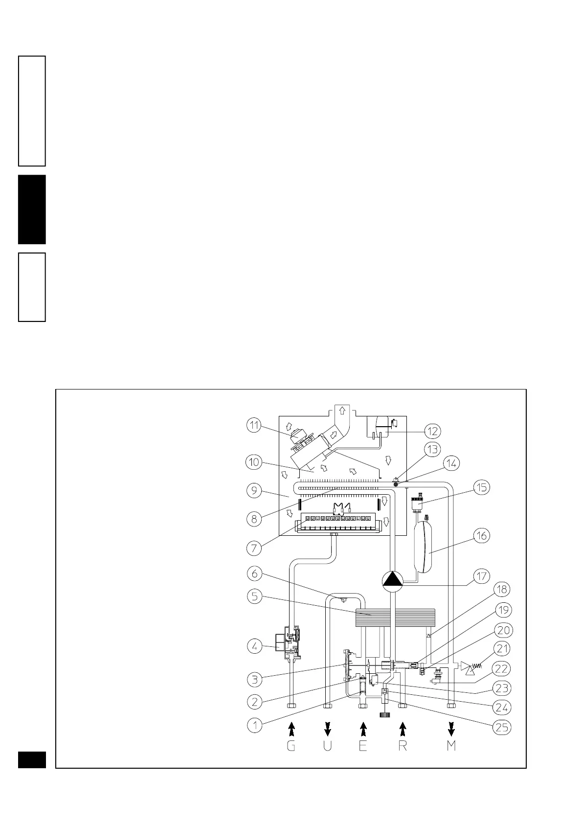
3.1 Eolo Maior @ hydraulic circuit diagram.
3
BOILER START-UP
(PRELIMINARY TESTING)
To start up the boiler, proceed as follows:
- ensure that the declaration of conformity of instal-
lation is supplied with the appliance;
- ensure sealing efficiency of the gas intake circuit
with the shutoff valves closed and then with the
valves open and the gas valve deactivated
(closed); the meter must not indicate gas transfer
for at least ten minutes;
- ensure that the gas used corresponds to specifi-
cations for the boiler;
- ensure connection to a 30V-50Hz power mains,
correct L-N polarity and the earthing connection;
- verify if heating system is water filled, checking that
manometer pointer indicate 1÷1,2 bar of pressure;
- verify if automatic air vent cap is open and that
heating system is well degasified;
- switch on the boiler and ensure correct ignition;
- ensure that the maximum, intermediate and mini-
mum gas flow rate and relative pressure values
conform to specifications in the booklet on page
30-31;
- ensure activation of the safety device in the event
of gas supply failure, as well as the relative activa-
tion time;
- ensure activation of the main switch downstream
of the boiler and inside the boiler;
- check that the intake and/or exhaust terminals are
not blocked;
- ensure activation of the safety pressure switch in
the event of air supply failure;
- ensure activation of all regulation devices;
- seal the gas flow rate regulation devices (if set-
tings are modified);
- ensure production of hot domestic water;
- ensure sealing efficiency of water circuits.
- ensure adequate ventilation and/or aeration of the
boiler environment.
If any checks/inspection give negative results, do not
start the boiler.
Key:
1 - Sanitary min. flow shutter
2 - Flow limiter
3 - 3 way hydraulic valve
4 - Gas valve
5 - Sanitary heat exchanger
6 - Sanitary NTC sensor sensor
7 - Main burner
8 - Primary heat exchanger
9 - Sealed chamber
10 - Flue hood
11 - Flue extraction fan
12 - Fan safety pressure switch
13 - Central heating NTC sensor
14 - Over heat safety thermostat
15 - Automatic air vent valve
16 - Expansion vessel
17 - Circulating pump
18 - One-way valve
19 - Automatic by-pass
20 - Automatic by-pass exclusion stem
21 - 3 bar safety valve
22 - Water pressure switch
23 - Sanitary micro switch
24 - Filling group
G - Gas supply
U - Hot domestic water outlet
E - Domestic water inlet
R - System return
M - System delivery