INSTALLER
USER
TECHNICIAN
16
1.7 Chimneys/Flues.
General notes. A chimney/flue used to exhaust com-
bustion products must be designed as follows:
- ducting must ensure sealing of combustion prod-
ucts, be waterproof and insulated;
- construction in incombustible material suitable to
resist normal mechanical stress, heat and action
of combustion products or condensation;
- ducting routed vertically without reductions/throt-
tles;
- adequate insulation to avoid condensation or cool-
ing of flue gas, in particular if installed outside the
building or in rooms without heating;
- be adequately spaced, or, be fitted with an air jacket
for insulation from zones with combustible and/or
easily flammable materials;
- installation of a solid materials collection unit be-
low the first flue channel at a height of at least
500mm, fitted with a metal airtight door;
- designed with an internal circular, square or rec-
tangular section (in that latter two cases with
rounded angles with a radius no less than 20 mm).
Hydraulically equivalent sections are also admit-
ted;
- installation of a chimney terminal at the top of the
flue in compliance with specifications below and in
compliance with standards;
- without mechanical suction devices installed at the
top of the duct;
- in flues routed inside or against inhabited build-
ings, there must be no risk of pressure surges.
Chimney caps. These devices are installed on sin-
gle or multiple flues, to facilitate dispersion of com-
bustion products also in adverse weather conditions
and prevent deposit of foreign matter. Chimney caps
must meet the following requirements:
- useful output section no less than double that of
the flue/chimney;
- suitably designed to prevent penetration of rain or
snow in the flue/chimney;
- designed to ensure constant exhaust of combus-
tion products with any direction or angle of wind.
The outlet height, corresponding to the height of the
top of the flue/chimney, regardless of chimney caps,
must be outside the “backflow zone”, to avoid the
risk of counterpressure that prevents the free release
of combustion products into the atmosphere. There-
fore always observe the minimum heights indicated
in the figures in standards.
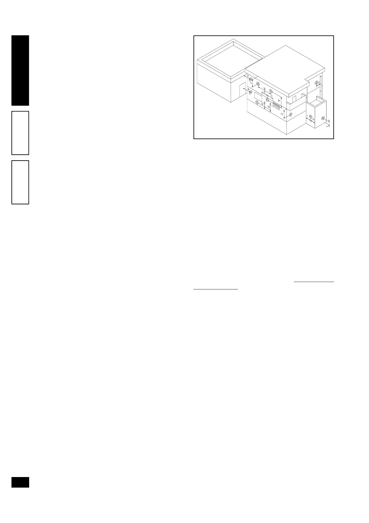
Positioning the draft terminals. Draft terminals
must:
- be installed on external perimeter walls of the build-
ing;
- be positioned (see figure) according to the mini-
mum distances specified in current technical
standards.
Fumes exhaust on natural draught appliances in
open top closed environments. In spaces closed
on all sides with open tops (ventilation pits, light wells,
inner courtyards, etc.), direct discharge of fumes is
allowed for natural or forced draught gas appliances
with a heat output from 4 to 35 kW, provided the speci-
fications of current technical standardsare complied
with (UNI 7129 par. 4.7).
1.8 System filling.
Once the boiler is connected, proceed with system
filling via the filling valve (see figure page 20).
Filling is performed at low speed to ensure release
of air bubbles in the water via the boiler and heating
system vents.
The boiler is equipped with an automatic air vent
positioned on the expansion vessel, that is in the rear
side of combustion sealed chamber. Check that the
cap is loosened and open the vent valves on the ra-
diators and close only when water is delivered.
Close the filling valve when the boiler pressure gauge
indicates approx. 1,2 bar.
N.W.: During this operation, activate the circulation
pump at regular intervals by means of the main switch
on the control panel. Vent the circulation pump by
loosening the front cap and keeping the motor run-
ning.
Tighten the cap on completion.
1.9 Gas system start-up.
To start up the system proceed as follows:
- open windows and doors;
- avoid presence of sparks or naked flames;
- vent all air from pipelines;
- check gas intake sealing efficiency with the boiler
gas shutoff valve closed, checking that there is no
gas transfer for at least 10 minutes.
1.10 Boiler start-up (ignition).
The following conditions are required for boiler start-
up:
- ensure gas intake sealing efficiency with the shutoff
valves closed and subsequently open with gas
valve closed over an interval of 10 minutes in which