Il Kit comprende:
N°1 - Guarnizione scarico (4)
N°1 - Guarnizione aspirazione (5)
N°1 - Guarnizione (6)
N°1 - Rosone (7)
N°1 - Terminale concentrico aspirazione/scarico Ø60/100 (8)
N°1 - Tappo di chiusura (9)
N°1 - O-ring (11)
C32
1-16
2
1
3
5
8
10
9
11
4
6
7
11
INSTALLERUSER
MAINTENANCE TECHNICIAN
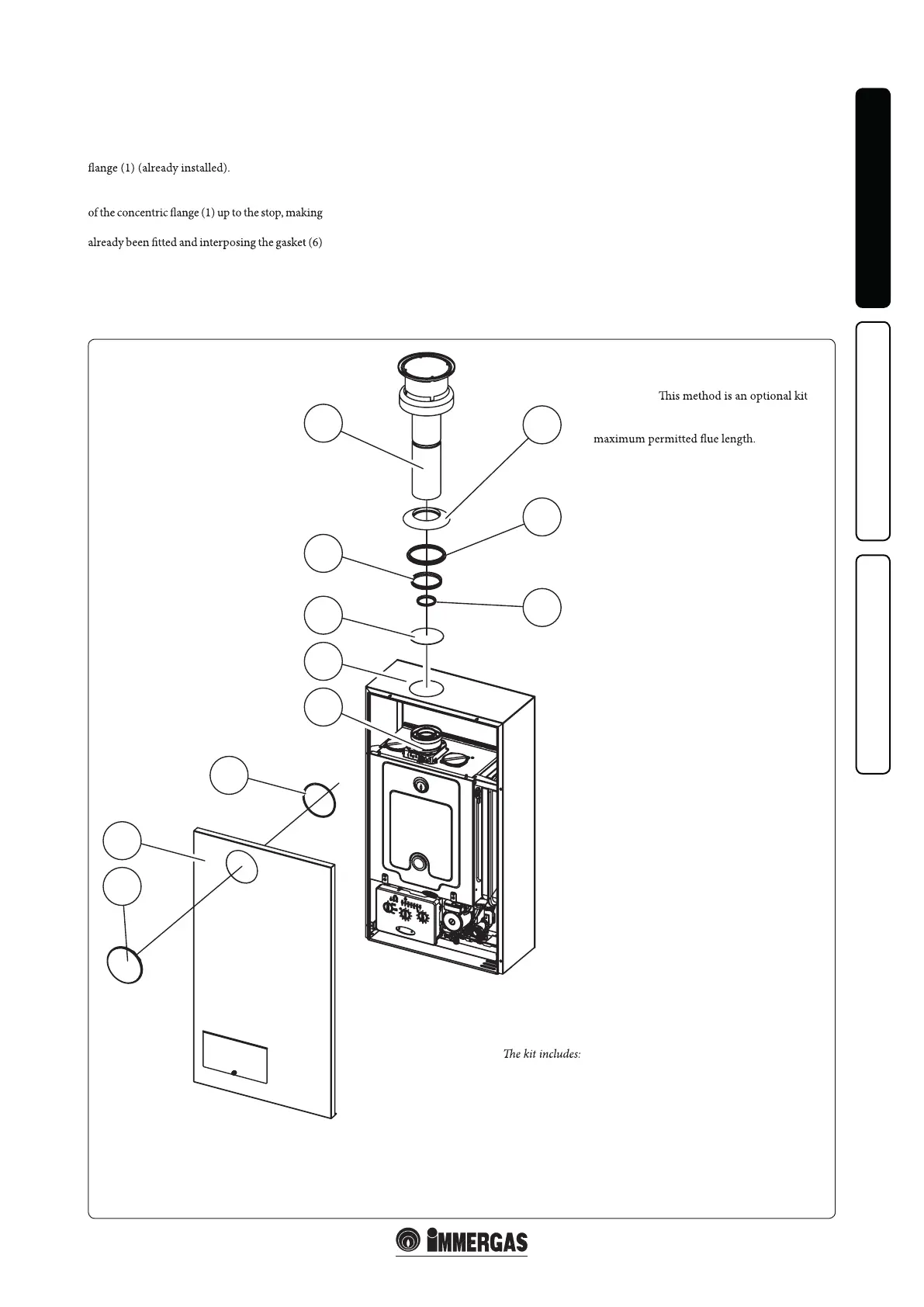
Vertical intake / exhaust kit Ø 60/100.
Kit assembly (Fig. 1-16):
Remove the knockout hole plug (3) from the
casing front (2).
Install the gaskets (4) and (5) in the concentric
Couple the concentric intake / exhaust pipe (8)
with the male end (smooth) into the female end
sure that the external wall sealing plate (7) has
on the casing front (2); this will ensure proper
sealing and joining of the elements.
Fit the cover (9) on the casing front (10) using
the gasket (11).
Mount the casing front (10) referring to Paragr.
3.14.
(Product code 3.023758) available only
from Hunt Heating and can be extended to the
No. 1 - Exhaust gasket (4)
No. 1 - Intake gasket (5)
No. 1 - Gasket (6)
No. 1 - Wall sealing plate (7)
No. 1 - Concentric intake/exhaust terminal Ø 60/100 (8)
No. 1 - Pipe closure cap (9)
No. 1 - O-ring (11)
Please note:
Flue terminal locations must
comply with AS 5601.