3-5
A
A
8
B
B
7
Part. B
5
5
7
Part. A
3
6
7
A
A
2
6
1
4
22
INSTALLER
USER
MAINTENANCE TECHNICIAN
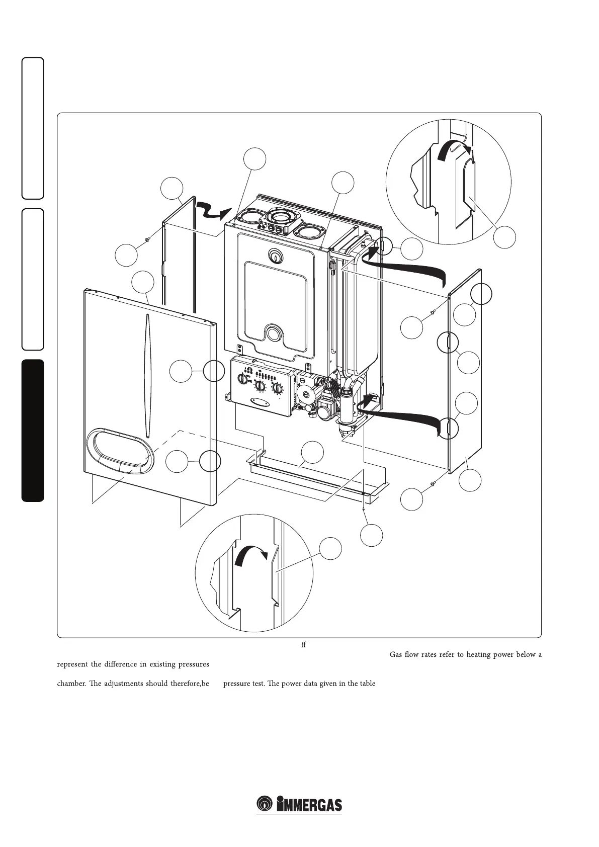
3.15 CASING REMOVAL.
To facilitate boiler maintenance and to access
the control panel, the casing can be completely
removed as follows:
- remove the lower grid (1) by loosening the 4
lower screw fasteners (2);
- remove the front (3) of the boiler by pushing it
upwards and at the same time pull it towards
yourself to release it from the lateral hooks (4)
and upper ones (5);
Det. B
Det. A
3.16 VARIABLE HEAT POWER.
N.B.: the pressures indicated in the tables
between the gas valve outlet and the combustion
- remove the sides (6) by loosening the screws
(7) and pulling towards yourself to free the side
from the seat (8) (Fig. 3-5).
carried out using a di
erential manometer
(small "U"-shaped column or digital manometer)
with the probes inserted in the pressure test gas
valve outlet and on the sealed chamber positive
is obtained with 0.5m long intake/exhaust pipe.
temperature of 15°C and pressure of 1013 mbar.
Burner pressure values refer to use of gas at 15°C.