1- 18
13
INSTALLERUSER
MAINTENANCE TECHNICIAN
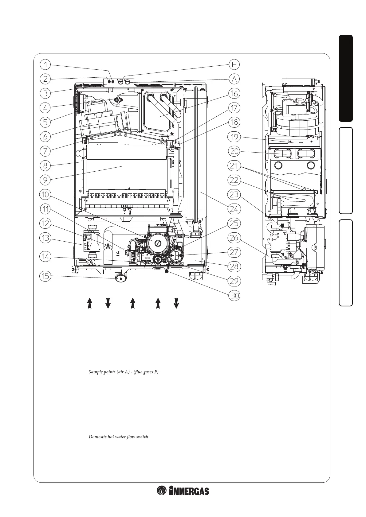
1.17 BOILER COMPONENTS.
Key:
1 - Negative signal pressure point
2 - Positive signal pressure point
3 -
4 - Flue safety thermostat
5 - Flue pressure switch
6 - Fan
7 - Condensate control level probe
8 - Sealed chamber
9 - Combustion chamber
10 - Boiler pump
11 - System pressure switch
12 - Domestic hot water probe
13 - Gas valve
14 -
15 - Manometer
16 -
17 -
Flow probe
18 -
Safety thermostat
19 -
Flue hood
20 -
Primary heat exchanger
21 -
Ignition and detection electrodes
22 -
Burner
23 -
Air vent valve
24 -
System expansion vessel
25 -
3 bar safety valve
26 -
DHW heat exchanger
27 -
3-way valve (motorised)
28 -
Condensate drain trap
29 -
By-pass
System draining valve
GAS DHW COLD
INLET
RETURN
FLOW
N.B.: Schematic shown here is of HE 30 COMBI INTERNAL.
e HE 30 COMBI EXTERNAL has identical component layout.
30 -
Condensing heat exchanger