12
INSTALLERUSER
MAINTENANCE TECHNICIAN
Head available to the system.
1.12 SYSTEM FILLING.
Once the boiler is connected, proceed with
system
ling via the ling valve (Fig. 2-2).
Filling is performed at low speed to ensure
release of air bubbles in the water via the boiler
and heating system vents.
on the circulator. Check if the cap is loose. Open
the radiator air vent valves.
Close radiator vent valves when only water
escapes from them.
indicates approx. 1.2 bar.
N.B.: during these operations start/up the
circulation pump at intervals, acting on the main
switch positioned on the control panel. Vent the
circulation pump by loosening the front cap and
keeping the motor running. Only open for a few
1.13 FILLING THE CONDENSATE TRAP.
On
rst lighting of the boiler combustion
products may come out the condensate drain;
with condensate to the correct level preventing
the passage of combustion products.
1.14
To start up the system, make reference to the
the start-up operations into three categories: new
In particular, for new gas systems:
- open windows and doors;
-
- bleed all air from pipelines;
- check that the internal system is properly sealed
1.15
- check that the internal system is properly sealed
- ensure that the type of gas used corresponds to
boiler settings;
- switch the boiler on and ensure correct ignition;
-
pressure values comply with those given in the
manual (Par. 3.16);
- ensure that the safety device is engaged in the
event of gas supply failure and check activation
time;
- check the intervention of the main switch
located upstream from the boiler and in the
boiler;
- check that the concentric intake-exhaust
one of the checks should be negative.
N.B.: the boiler preliminary check must be carried
boiler warranty is valid as of the date of testing.
user.
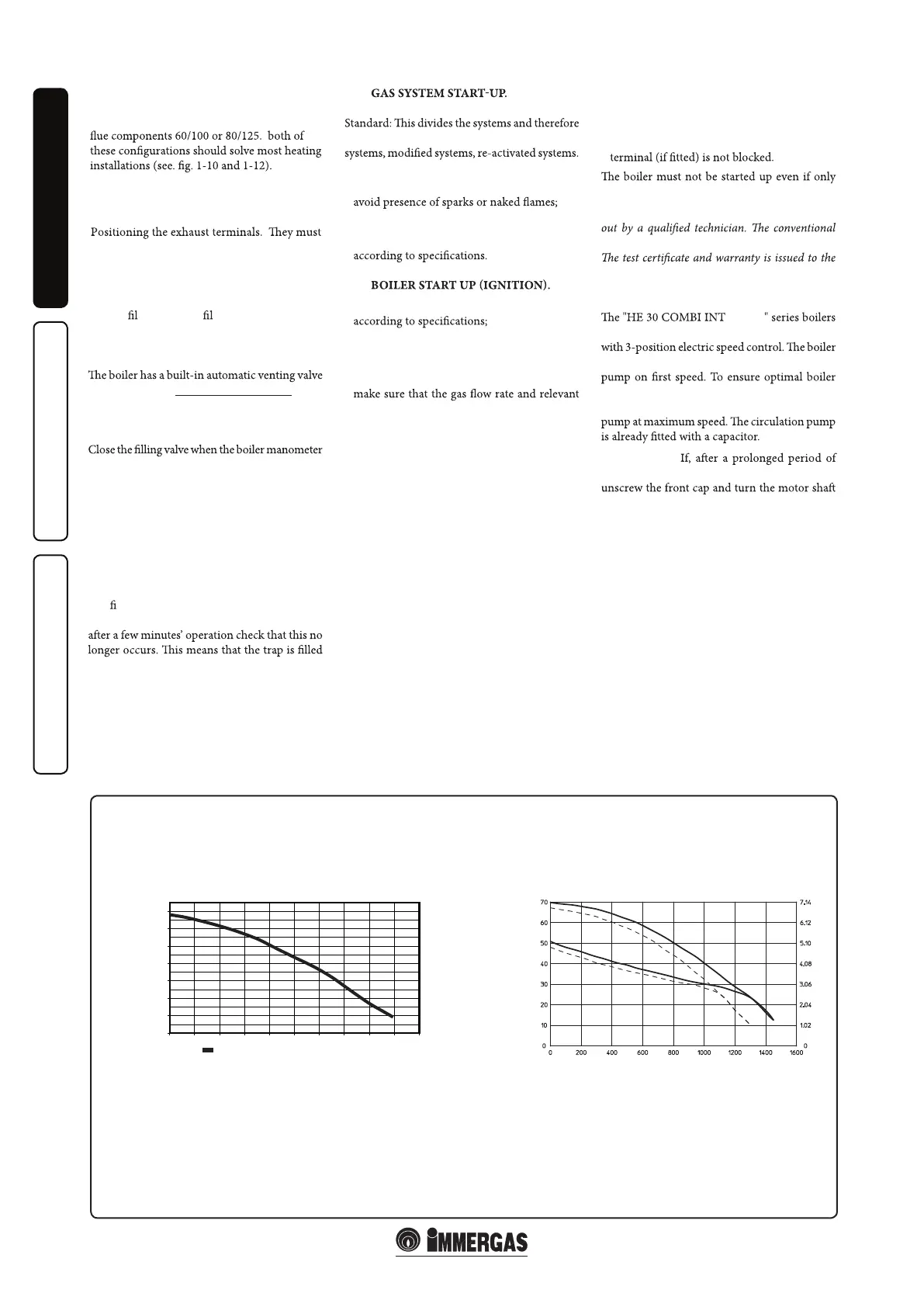
1.16 CIRCULATION PUMP.
are supplied with a built-in circulation pump
does not operate correctly with the circulation
operation, in the case of new systems (single
pipe and module) it is recommended to use the
Pump release.
inactivity, the circulation pump is blocked,
using a screwdriver. Take great care during this
operation to avoid damage to the motor.
N.B.: Whist the 80mm twin pipe system is
approved for the HE 30 COMBI INT/EXT
boiler, Hunt Heating only stock the concentric
In the event that a twin pipe system is required,
please contact Hunt Heating and we can design
this sytem to meet your requirements.
seconds at a time.
1-17
0,0
1,0
2,0
3,0
4,0
5,0
6,0
7,0
0,0
500
Flow rate (L/h)
Head H (mwc )
H for 7m
1000
1500
2000
2500
3000
3500
4000
4500
5000
Circulation Pump Head / Flow graph - Grundfos 15-70
A
B
C
D
A = Head available to the system at maximum speed with by-pass excluded.
B = Head available to the system at maximum speed with by-pass inserted.
C = Head available to the system at second speed with by-pass excluded.
D = Head available to the system at second speed with by-pass inserted.
Flow rate (l/h)
Head (m H
2
O)
Head (kPa)
Head available to the system.
terminate externally of the building.
- Be positioned according AS 5601.
/ EXT