C12
1-13
4
5
6
1
2
3
8
9
10
7
10
INSTALLERUSER
MAINTENANCE TECHNICIAN
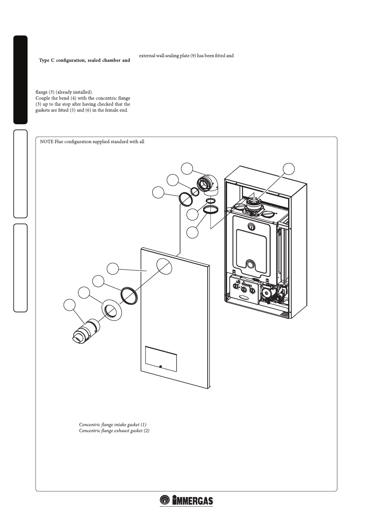
1.8 INSTALLATION OF INTAKE /
EXHAUST TERMINALS FOR
•
fan assisted.
Horizontal intake - exhaust terminal Ø60/100
(supplied as standard). Assembly (Fig. 1-9):
install the gaskets (1) and (2) in the concentric
Mount the casing front (7) referring to
Paragraph 3.14.
Couple the terminal pipe (10) with the male end
(smooth) into the female end (with lip seals) of
the bend (4) up to the stop, making sure that the
checking it is on the casing front (7) and gasket
(8); this will ensure proper sealing and joining
of the elements.
Components:
No. 1 -
No. 1 -
No. 1 - 90° concentric bend (4)
No. 1 - 90° concentric bend exhaust gasket (5)
No. 1 - 90° concentric bend intake gasket (6)
No. 1 - Gasket (8)
No. 1 - External wall sealing plate (9)
No. 1 - Concentric intake/exhaust terminal Ø 60/100 (10)
Flue kit complete 60/100 Australia code: 3.023633
HE external boilers.
HE 30 COMBI EXTERNAL
e Immergas boiler when exposed to
extreme wind conditions will deactivate the
gas and combustion operation. When
conditions change the boiler will safely, and
automatically resume normal operation and
performance.
No lock out light will illuminate and no
requirement for manual reset. A terminal kit
is available if the appliance is to be installed in
applications / areas that extreme wind
conditions are common. Please refer to Hunt
Heating Customer Service.