1
2
3
4
5
6
7
8
9
30
3
2
INSTALLATION DIAGRAMS
If you are using a Comando Amico RemotoV2 (CAR
V2
) or Super CAR zone control remote control, it must be connected directly to
the boiler (see instructions in the boiler booklet).
e CAR
V2
or Super CAR will control the zone, pre-dened as main on the manifold.
CAR
V2
or Super CAR must be set up with on-o mode if connected to boilers other than Victrix Superior (2022) (see the relative in-
struction booklet).
N.B.: combined with the Victrix Superior (2022) range of boilers, the jumper on the RT connections of zone 1 (managed remotely)
must be maintained (or used for contacts of zone shutter valves).
N.B.: combined with boilers other than Victrix Superior (2022), the jumper on the RT connections of the zone dened as main must
be eliminated.
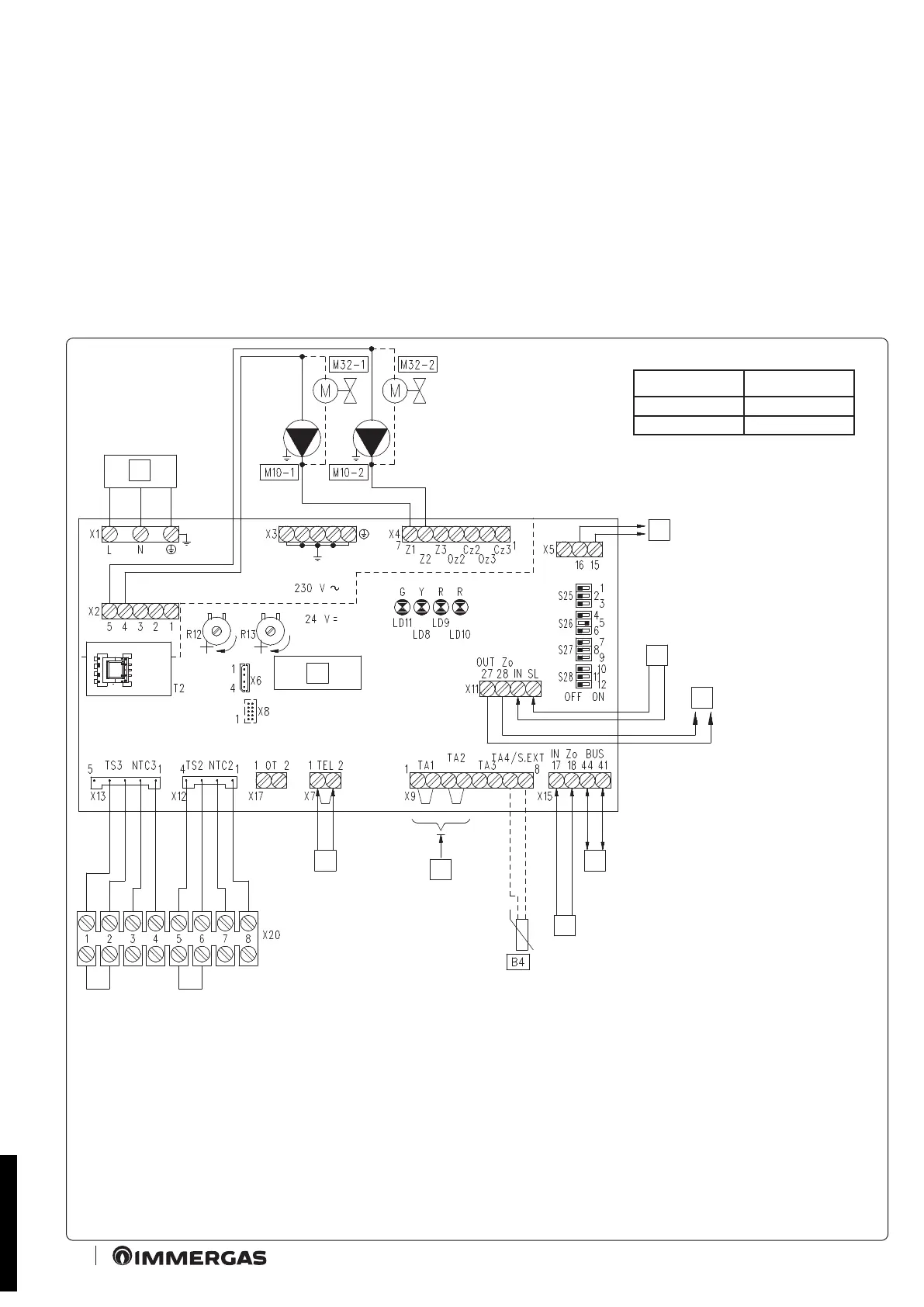
2.1 WIRING DIAGRAM FOR USING THE KIT ON A SYSTEM SPLIT INTO 2 HOMOGENEOUS ZONES
Zone Type
Zone 1 Direct
Zone 2 Direct
Key:
B4 - External probe (optional)
M10-1 - Zone 1 circulator
M10-2 - Zone 2 circulator
M32-1- Zone 1 valve
M32-2- Zone 2 valve
R12 - Zone 2 low temperature ow regula-
tion trimmer
R13 - Zone 3 low temperature ow regula-
tion trimmer
S25 - P.C.B. setting selector
S26 - P.C.B. setting selector
S27 - P.C.B. setting selector
S28 - P.C.B. setting selector
T2 - Zones control unit low voltage feeder
1 - 230 Vac 50 Hz power supply
2 - Central heating request outlet to boiler
or other zones control unit
3 - Central heating request inlet from
other zones control unit
4 - Zones signal state outlet for other zones
control unit
5 - Connection to marker safety thermostat
6 - Connections to ON/OFF room thermostats
7 - Zones signal state inlet from boiler or
other zones control unit
8 - DIM BUS connection to boiler
9 - Zones control unit
BK - Black
BR - Brown
BL - Blue
GY - Grey
R - Red
Y/G - Yellow/Green
STD.009285/001
 Loading...