1
2
3
4
5
6
7
8
9
32
Zone Type
Zone 1 Direct
Zone 2 Direct
Zone 3 Direct
5
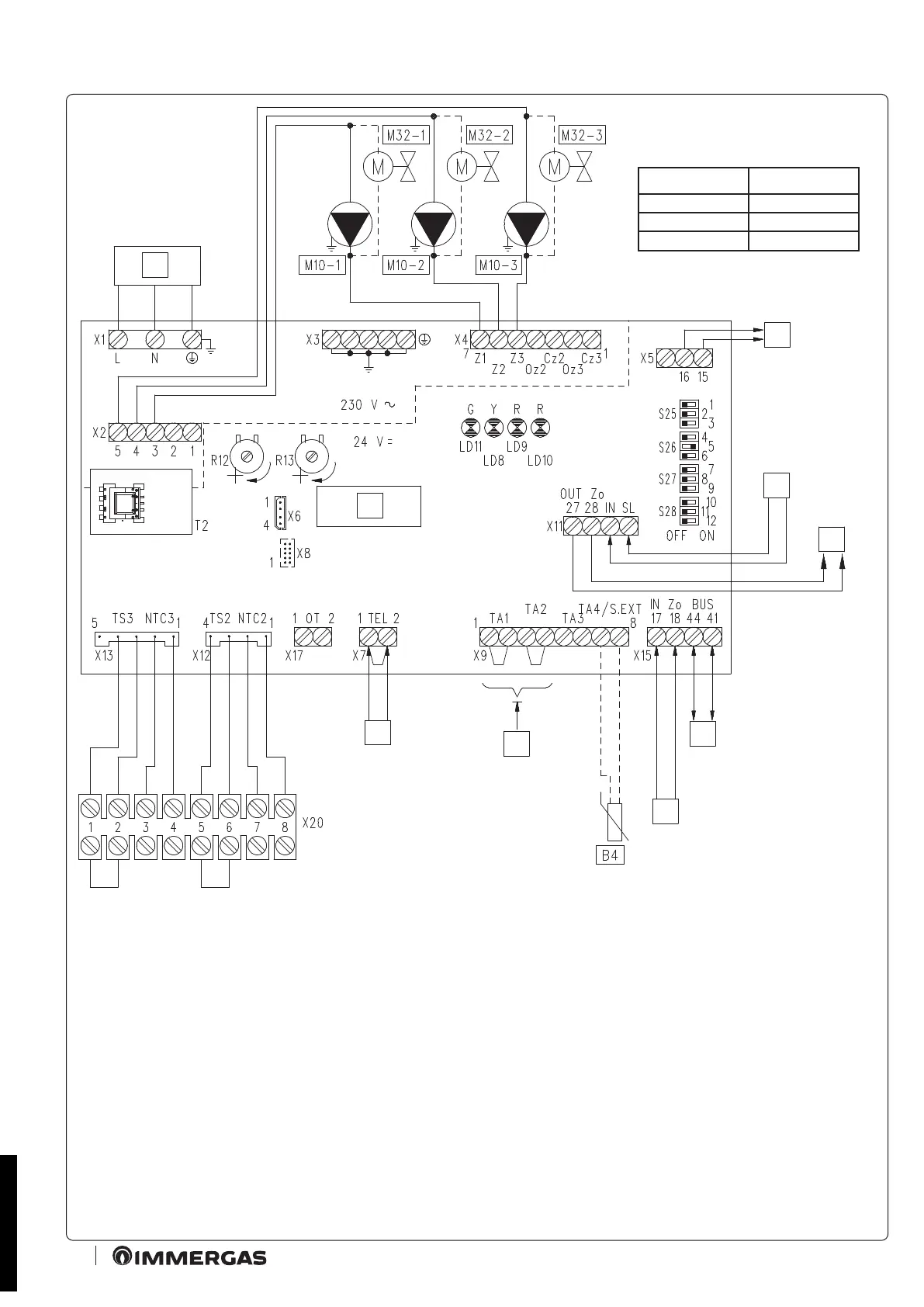
2.2 WIRING DIAGRAM FOR USING THE KIT ON A SYSTEM SPLIT INTO 3 HOMOGENEOUS ZONES
Key:
B4 - External probe (optional)
M10-1 - Zone 1 circulator
M10-2 - Zone 2 circulator
M10-3 - Zone 3 circulator
M32-1- Zone 1 valve
M32-2- Zone 2 valve
M32-3- Zone 3 valve
R12 - Zone 2 low temperature ow
regulation trimmer
R13 - Zone 3 low temperature ow
regulation trimmer
S25 - P.C.B. setting selector
S26 - P.C.B. setting selector
S27 - P.C.B. setting selector
S28 - P.C.B. setting selector
T2 - Zones control unit low voltage feeder
1 - 230 Vac 50 Hz power supply
2 - Central heating request outlet to
boiler or other zones control unit
3 - Central heating request inlet from
other zones control unit
4 - Zones signal state outlet for other
zones control unit
5 - Connection to marker safety
thermostat
6 - Connections to ON/OFF room
thermostats
7 - Zones signal state inlet from boiler or
other zones control unit
8 - DIM BUS connection to boiler
9 - Zones control unit
BK - Black
BR - Brown
BL - Blue
GY - Grey
R - Red
Y/G - Yellow/Green
STD.009285/001
 Loading...