1
41
14
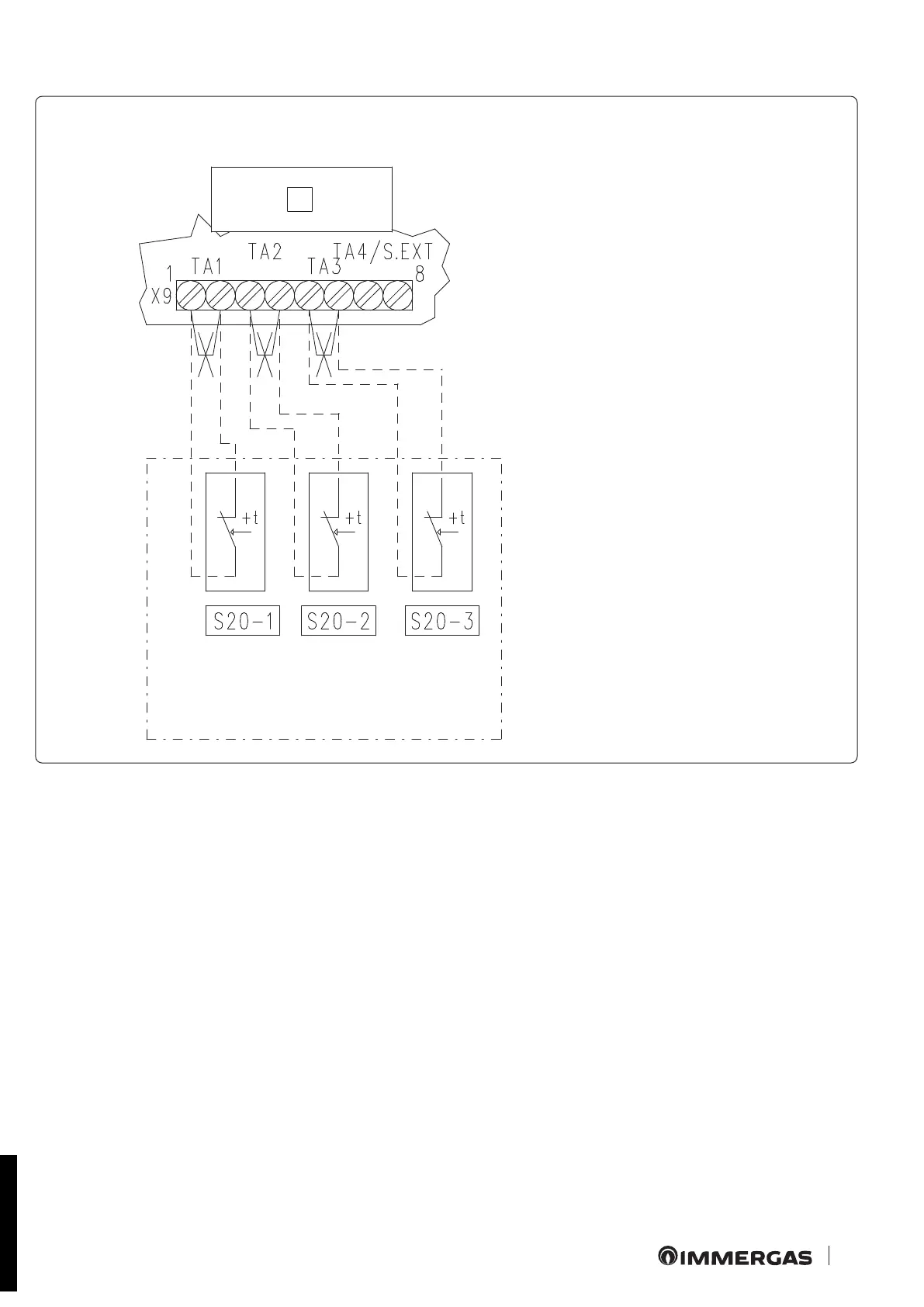
N.B.: all components represented in this diagram are optional.
Every zone can be controlled by the relative room thermostat.
On connecting the room thermostats, it is necessary to eliminate the jumpers present on the X9 terminal board of the zones control unit.
If the Zones control unit is connected via BUS to Victrix Superior (2022) boilers, the activation of the zones is determined by the closure
of the Room ermostats and by the program on the Boiler menu (see boiler instruction booklet).
Key:
S20-1 - Zone 1 room thermostat
S20-2 - Zone 2 room thermostat
S20-3 - Zone 3 room thermostat
1 - Zones control unit
2.8 CONNECTING THE ZONES CONTROL UNIT KIT TO ON/OFF ROOM THERMOSTATS
WIRING DIAGRAM TO CONNECT THE ZONES CONTROL UNIT KIT TO ON/OFF ROOM THERMOSTATS
STD.009285/001
 Loading...