X1
X2
R12 R13
X6
X15
T2
X13 X12 X17 X7 X9
X11
X8
H2
H3
H11 H8
H4 H5 H6 H7
S25
3 2 14 5 69 8 7121110
S26S27S28
H9 H10
H1
X3
X4 X5
L N
1
3
4
7
8
56
2
46
17
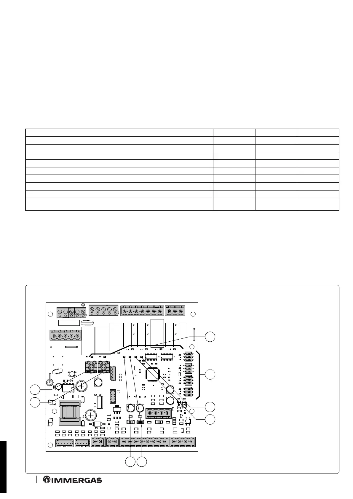
Warnings
Various LEDs are present on the board to display the functioning status and to indicate any anomalies.
e LEDs from 1 to 7 (1 Fig. 17) identify switch-on of the relative relay:
- Zone 1 LED H1 activation (high temperature)
- Zone 2 LED H2 activation (low temperature)
- Zone 3 LED H3 activation (optional)
- LED H4 mixed zone 2 mixer opening.
- LED H5 mixed zone 2 mixer closure
- Zone 3 mixing valve opening LED H6 (optional)
- Zone 3 mixing valve closing LED H7 (optional)
e LED H11 signals that the zone management board is powered.
LEDs 8, 9 and 10 indicate the functioning status of the board:
Warning H8 H9 H10
CH request presence ON OFF OFF
Disabling of active zones ON L OFF OFF
Zone 2 safety thermostat intervention OFF ON OFF
Mixed zone 2 probe fault OFF ON L OFF
Zone 3 safety thermostat intervention OFF OFF ON
Mixed zone 3 probe fault OFF OFF ON L
DIM BUS Anomaly OFF ON A ON A
Zones control unit kit communication present OFF OFF ON F
Intervention of the marker safety thermostat kit OFF ON V OFF
Key:
ON = ON
OFF = OFF
ON L = Slow ashing (0.6 s on, 0.6 s o)
ON V = Fast ashing (0.3 s on, 0.3 s o)
ON F = Flash ashing (0.2 s on, 1 s o)
ON A = Alternate ashing
Zone management P.C.B.
Key:
1 - Relay functioning signal LED (H1 - H7)
2 - Zones management board functioning mode
selectors
3 - Board functioning status signal LED
(H10)
4 - Board functioning status signal LED
(H9)
5 - Board functioning status signal LED
(H8)
6 - Board power supply signal LED (H11)
7 - Mixed zone 3 flow temperature adjustment
trimmer
8 - Mixed zone 2 flow temperature adjustment
trimmer
STD.009285/001
 Loading...