(A)
(B)
9
16
INSTALLER
USER
MAINTENANCE TECHNICIAN
1.11 IMMERGAS FLUE SYSTEMS.
Immergas supplies various solutions separately from the boilers
regarding the installation of air intake terminals and ue exhaust,
which are fundamental for boiler operation.
ATTENTION:
the boiler must be installed exclusive-
ly with an original Immergas “Green
Range” inspectionable air intake system and
ue gas extraction system made of plastic,
with the exception of the C6 conguration, as
required by the regulations in force and by the
product’s approval.
is ue can be identied by an identication
mark and special distinctive marking bearing
the note "only for condensation boilers".
e plastic pipes cannot be installed outdoors,
for tracts longer than 40 cm, without suitable
protection from UV rays and other atmos-
pheric agents.
• Resistance factors and equivalent lengths.
Each ue component has a Resistance Factor based on exper-
imental tests and specied in the table below. e Resistance
Factor for individual components is independent from the type
of boiler on which it is installed and has a dimensionless size. It
is however, conditioned by the temperature of the uids that pass
through the pipe and therefore, varies according to applications
for air intake or ue exhaust. Each single component has a resist-
ance corresponding to a certain length in metres of pipe of the
same diameter; the so-called equivalent length, can be obtained
from the ratio between the relative Resistance Factors.
All boilers have an experimentally obtainable maximum Re-
sistance Factor equal to 100.
e maximum Resistance Factor allowed corresponds to the
resistance encountered with the maximum allowed pipe length
for each type of Terminal Kit. is information allows calcula-
tions to be made to verify the possibility of setting up various
ue congurations.
Note: to dimension the ue ducting using commercial components,
refer to the table of combustion parameters (Paragraph 4.2).
•
Positioning the gaskets (black) for “green range” ue systems.
Position the gasket correctly (for bends and extensions) (Fig. 9):
- gasket (A) with notches, to use for bends;
- gasket (B) without notches, to use for extensions.
N.B.: if necessary, to ease the push-tting, spread the elements
with commonly-used talc.
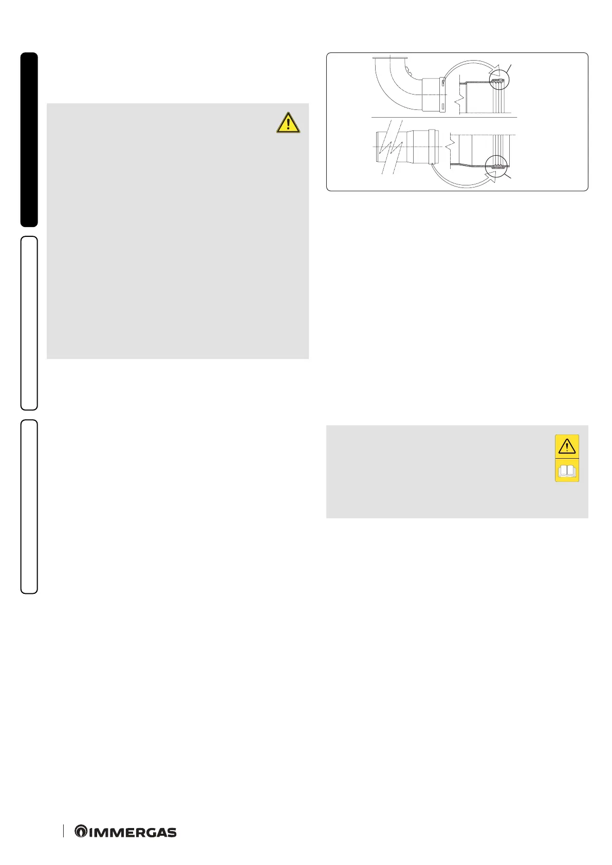
•
Extension pipes and concentric elbows push-ttings.
To install push-tting extensions with other elements of the ue
extraction elements assembly, proceed as follows: Install the con-
centric pipe or elbow with the male side (smooth) on the female
side (with lip seal) to the end stop on the previously installed
element in order to ensure sealing eciency of the coupling.
N.B.: if the exhaust terminal and/or extension concentric pipe
needs shortening, consider that the internal duct must always
protrude by 5 mm with respect to the external duct.
N.B.: for safety purposes, do not obstruct the boiler intake/
exhaust terminal, even temporarily.
e various parts of the ue system must be checked
to ensure that they have been laid in such a way as
to prevent the coupled parts from detaching, in par-
ticular, the ue exhaust duct in the Ø80 separator kit
conguration. Should the aforesaid condition not be
adequately guaranteed, it will be necessary to use the
special clamp ring nut clip kit.
N.B.: when installing horizontal pipes, a minimum inclination
of 3% towards the boiler must be maintained, and a section clip
with pin must be installed every 3 metres.
 Loading...


