37
INSTALLER
USERMAINTENANCE TECHNICIAN
TECHNICAL DATA
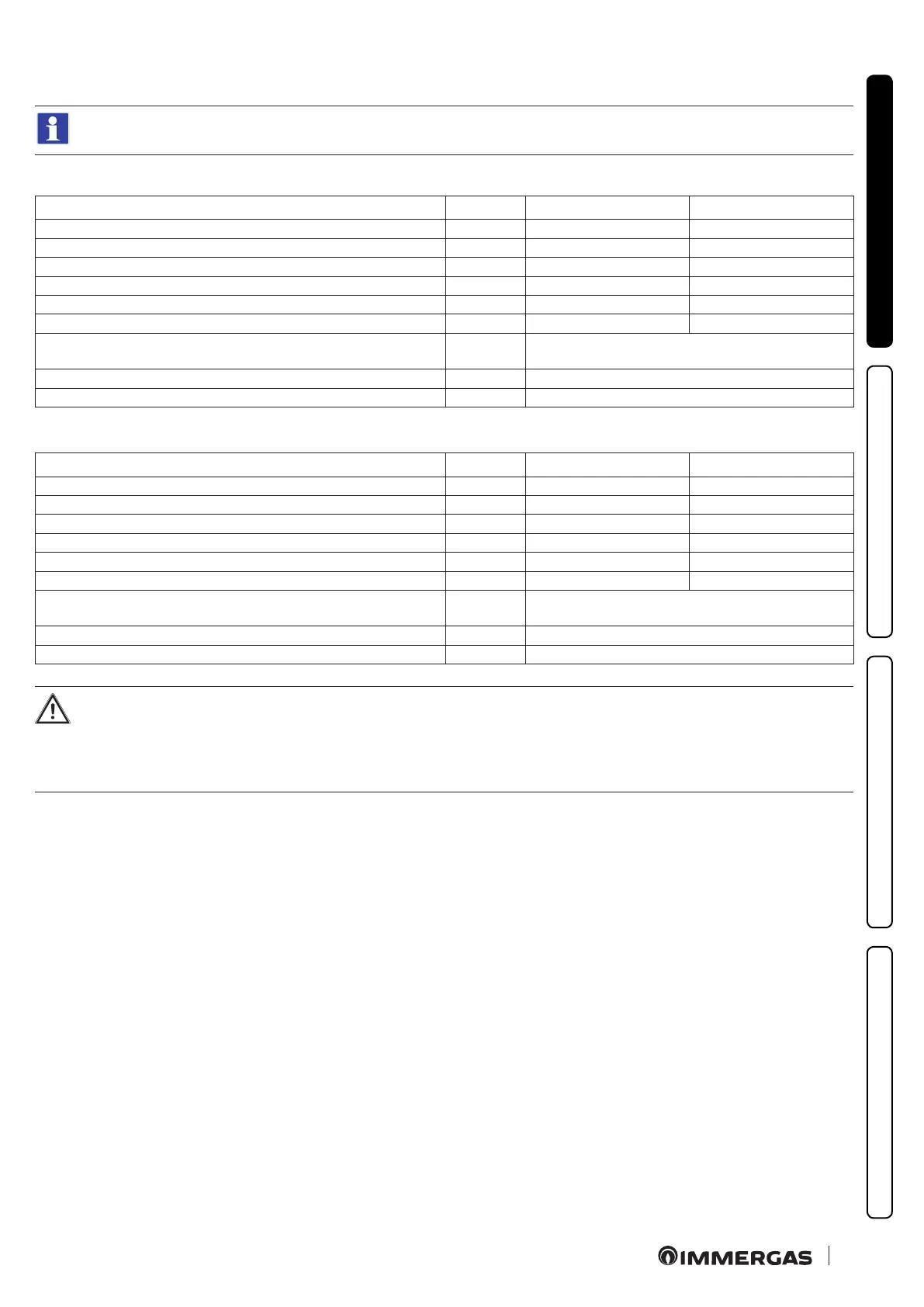
1.16 CONFIGURATION FOR C6 FLUE INSTALLATION
Appliance designed to be connected to a commercial exhaust/intake system.
Victrix Tera V2 24 PLUS EU
Gas type G20 G31
Flue temperature at maximum output °C 67,5 67
Flue gas mass at maximum power kg/h 40 41
Flue temperature at minimum output °C 58 56
Flue gas mass at minimum power kg/h 8 8
CO
2
at Q. max. % 9,1 (9,0 ÷ 9,4) 10,2 (10,0 ÷ 10,4)
CO
2
a Q. minimum % 8,5 (8,3 ÷ 8,7) 9,7 (9,5 ÷ 9,9)
Maximum head available at maximum power (maximum resistance
value of the commercial ue system)
Pa 163
Maximum head available at minimum power Pa 5
Maximum temperature that the exhaust pipes can reach °C 120
Victrix Tera V2 35 PLUS EU
Gas type G20 G31
Flue temperature at maximum output °C 72,5 73
Flue gas mass at maximum power kg/h 54 54
Flue temperature at minimum output °C 64 62
Flue gas mass at minimum power kg/h 11 11
CO
2
at Q. max. % 9,0 (8,9 ÷ 9,3) 10,2 (10,0 ÷ 10,4)
CO
2
a Q. minimum % 8,5 (8,2 ÷ 8,6) 9,6 (9,4 ÷ 9,8)
Maximum head available at maximum power (maximum resistance
value of the commercial ue system)
Pa 302
Maximum head available at minimum power Pa 9
Maximum temperature that the exhaust pipes can reach °C 120
- Ducts must withstand condensation (only for condensing models);
- Air intake ducts must withstand working air temperatures of up to 60°C;
- e maximum permissible percentage of ue gas recirculation in windy conditions is 10%.
- Suction and exhaust pipes cannot be installed on opposing walls;
- With ues in conguration C
6
discharge into pressurised ues is not permitted.