10
STZM@ ed 05/04 ZEUS Maior @
Technical DocumentationTechnical Documentation
e circuit consists of an atmospheric burner and a modulat-
ing type gas valve for gas combustion and flow regulation
respectively.
Operation.
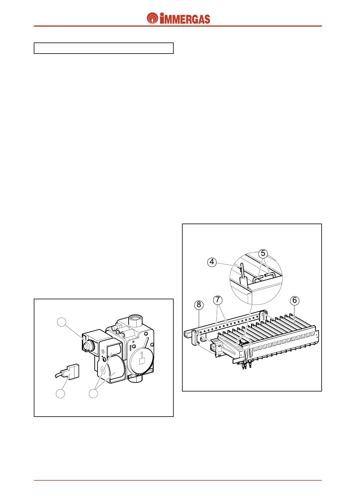
When the main coils (3) are electrically powered both shutters
inside the valve open, letting gas through to the burner.
Consequently, the flow rate/pressure in output is adjusted by
acting on the gas valve stabiliser by means of the modulating
coil (1).
e fuel is injected into the horizontal Venturi tubes (ramps)
through the burner nozzles (7). e air-gas mixture is created
inside these tubes that is ignited by the spark of the ignition
electrodes (5).
Modulating gas valve.
e gas valve (SIT 845) features two main coils (3) controlled
by the electrical circuit, and a modulation coil (1) controlled
by the modulation board.
e maximum and minimum outlet pressures can be set with
this valve (see gas settings).
Main electric coils (3).
ey are two ON-OFF type coils powered (230 Vac) by the
ignition control unit when the burner has to be ignited.
ey are electrically connected in parallel and supplied by
mains power through a connector (2).
Modulating coil (1).
This is a low voltage coil controlled by the modulation
board.
It controls the gas valve stabiliser and allows the outlet pres-
sure to be varied in a way proportionate to the DC running
through it.
Gas circuit.
Burner.
e burner consists of horizontal Venturi tubes (6) inside which
the gas is injected by an equal number of nozzles (7) mounted
on the manifold (8).
e number of nozzles, whose diameter varies according to the
type of gas used (see technical data) are 13 in the 21,000 kcal/h
versions and 15 in the 24,000 kcal/h versions.
Ignition occurs by means of a p.c.b. (ignition control unit) that
controls both the ignition (5) and detection (4) electrodes.
Ignition electrodes (5).
ey are controlled by the ignition control unit that produces
an electrical charge between their ends, igniting the air-gas
mixture when they come into contact.
ey are at the front of the burner.
Detection electrode (4).
is is controlled by the ignition control unit and detects
burner ignition.
It is located at the front of the burner near the ignition elec-
trodes.
 Loading...