14
STZM@ ed 05/04 ZEUS Maior @
Technical DocumentationTechnical Documentation
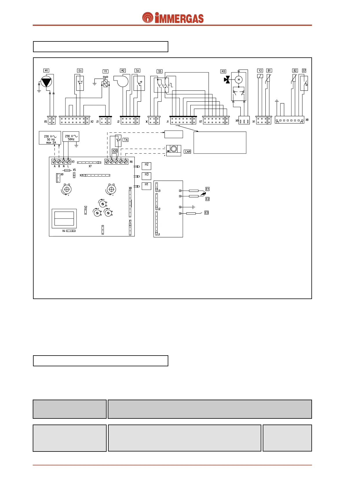
Electrical circuit.
e electrical circuit of the ZEUS Maior @ boiler is controlled
100% by a microprocessor controlled p.c.b. which controls
boiler functions.
230 V AC circuit.
Safety devices and controls.
Some of the control and safety devices work at mains voltage
(230 Vac) while others at low voltage.
It detects burner ignition, being hit by its flame.
It’s connected to the ignition control circuit’s detection circuit.
Detection electrode
(E3)
It interrupts power to the circuit when power input is over 3.15 A.
It is mounted on the modulation board.
Fuse
(F)
Fuse
3,15 AF 250 V
Legend:
B1 - NTC delivery probe
B2 - Domestic hot water NTC probe
CAR - Remote control (optional)
CZ - Zone control unit (optional)
E1-E2 - Ignition electrodes
E3 - Detection electrode
E4 - Safety thermostat
F - Line fuse
H1 - Gas supply valve LED
H2 - Block indicator LED
H3 - Mains LED
M1 - Circulator
M2 - Fumes fan
M3 - 3-way diverter valve
S4 - Flue pressure switch micro
S5 - Main switch
S7 - System pressure switch
TA - Room thermostat On/Off (optional)
X20 - TA or CAR inhibition jumper
Y1 - Gas valve
Y2 - Gas valve modulator
F
 Loading...