5
STZM@ ed 05/04 ZEUS Maior @
Technical Documentation
Technical Documentation
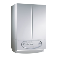
A = Head available to the system at top speed with the by-pass off
(adjustment screw tightened right down)
B = Head available to the system at top speed (screw tightened 1.5 turns
compared to the adjustment screw which is completely unscrewed)
C = Head available to the system at top speed with the by-pass open
(adjustment screw completely unscrewed)
Primary circuit (boiler circuit).
e primary circuit, with its control and safety devices, is
started each time either a central heating or domestic hot
water request is made.
Operation.
e heat contained in the fumes produced by combustion is
absorbed by the copper blades of the water-gas exchanger (8)
which, in turn, transfers it to the water circulating inside by
means of the boiler circulator (16).
e water is transferred directly to the system or it can be devi-
ated to the storage tank coil (2). is depends on what position
the electric 3-way diverter valve (20) is in which, according to
the request, either lets water flow through the system delivery
(M) and return (R) pipes or to the coil (2).
Head-flow rate graph.
e course of the curve that represents the flow rate/head ratio
depends on how the system by-pass is set which, according to
the position, gives the system a bigger or smaller head. e
characteristic curves, based on the by-pass setting, are shown
in the following graph.
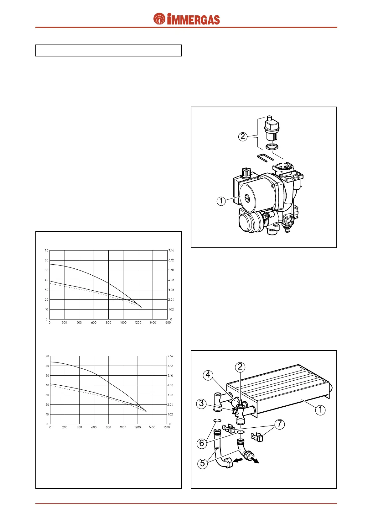
Boiler circulator (1).
e pump works on the primary circuit immediately after the
3-way diverter valve to which it is connected. It is part of the
integrated multifunction unit made in a composite material.
e automatic air vent (2) is housed on the body.
Primary exchanger (1).
is is a lamellar water-gas exchanger with copper tubes and
fins (96 fins in the ZEUS 21 version and 109 in the ZEUS 24
version) and at whose outlet (delivery) both the central heat-
ing NTC delivery probe (2) and the overtemperature safety
thermostat (3) are located.
e four pipes it is made of are connected in series (4).
It is connected to the circulator delivery and to the primary
circuit delivery by push-fitted pipes (5) and O rings (6) locked
with forks (7).
Head (kPa)
Flow rate Litres/h
A
Head (m H
2
O)
ZEUS 21 Maior @
Head (kPa)
Flow rate Litres/h
Head (m H
2
O)
ZEUS 24 Maior @
B
C
A
B
C
Delivery
Return