4
STZM@ ed 05/04 ZEUS Maior @
Technical DocumentationTechnical Documentation
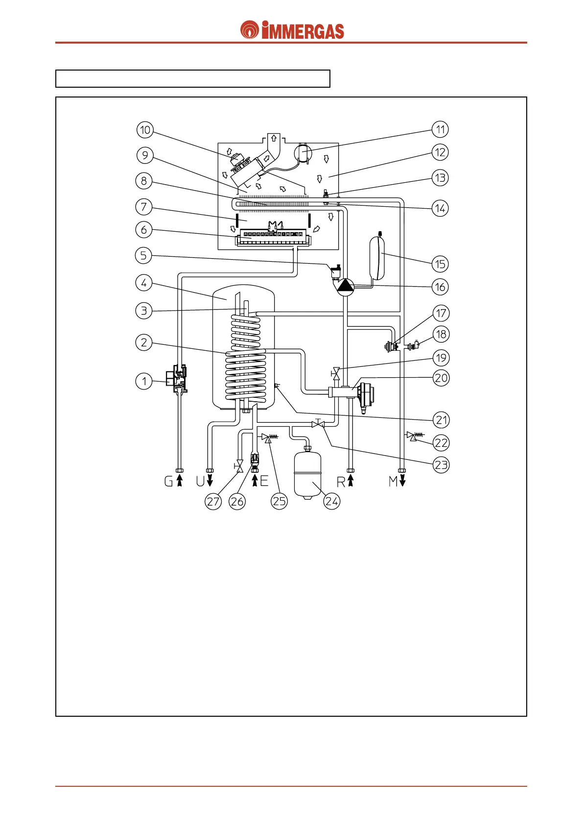
Hot water for central heating and domestic use is produced
by a primary and a secondary (d.h.w.) circuit that work as
required.
ZEUS Maior @ Hydraulic diagram.
Legend:
1 - Gas valve
2 - Stainless steel coil for the storage tank
3 - Magnesium anode
4 - Storage tank
5 - Automatic air vent
6 - Main burner
7 - Combustion chamber
8 - Primary exchanger
9 - Draught diverter
10 - Fumes expulsion fan
11 - Flue pressure switch
12 - Airtight chamber
13 - Central heating delivery NTC probe e limit
14 - Overtemperature safety thermostat
15 - Expansion tank
16 - Circulator
17 - Adjustable by-pass
18 - System water pressure switch (absolute)
19 - System draining cock
20 - Motorised 3-way diverter valve
21 - Domestic hot water NTC probe
22 - 3-bar safety valve
23 - Filling valve
24 - D.h.w. expansion tank
25 - 8-bar safety valve
26 - One-way valve
27 - Storage tank draining cock
R - System return
M - System delivery
G - Gas supply
U - Domestic hot water outlet
E - Domestic cold water inlet