13
STZM@ ed 05/04 ZEUS Maior @
Technical Documentation
Technical Documentation
Flue pressure switch (6).
It is located at the top, inside the airtight chamber and, by
means of the relative points, measures the difference in pres-
sure between the top of the draught diverter (where the fan
is installed and works) and the inside of the airtight chamber
itself.
e signal measured by the pressure switch varies according
to the length of the intake/exhaust ends and can be measured
by the relative pressure points located at the top of the airtight
chamber (9-10).
When the switch trips it causes a contact to switch that enables
or prevents burner ignition.
Triggering pressures
flue pressure switch
ON
Pa (mm H
2
O)
OFF
Pa (mm H
2
O)
ZEUS 21 Maior @ 36 (3.7) 44 (4.5)
ZEUS 24 Maior @ 52 (5.3) 42 (4.3)
Fan (5).
e extractor works downstream from the combustion cham-
ber and is secured vertically to the top of the hood (4) from
which it extracts the fumes, conveying them to the exhaust
pipes to which the boiler is connected. It guarantees the flow
of air inside the airtight chamber at the same time.
It is controlled by the adjustment board and basically its opera-
tion coincides with that of the burner.
Extraction and exhaust systems.
(see the extraction and exhaust ends instructions).
ZEUS Maior @ is designed to be connected to the intake/
exhaust coupling pipes and can be installed in the airtight
chamber or fan-assisted (type C) configuration or, with the kit,
in the open chamber fan-assisted (type B
22
) configuration.
As regards to the head losses of each accessory, for the various
possible combinations and use of the diaphragms to install ac-
cording to pipe length see the instructions for the extraction
and exhaust ends (boiler instruction booklet).
e accessories (curves, extensions and end pieces) are the couple-
on type and silicone lip seals guarantee sealing.
Open chamber and fan-assisted configuration
(type B
22
).
Using the relative kit, the open chamber fan-assisted configura-
tion of the ZEUS Maior @ boiler (type B
22
) can be installed
which means combustion air is extracted directly from the
room.
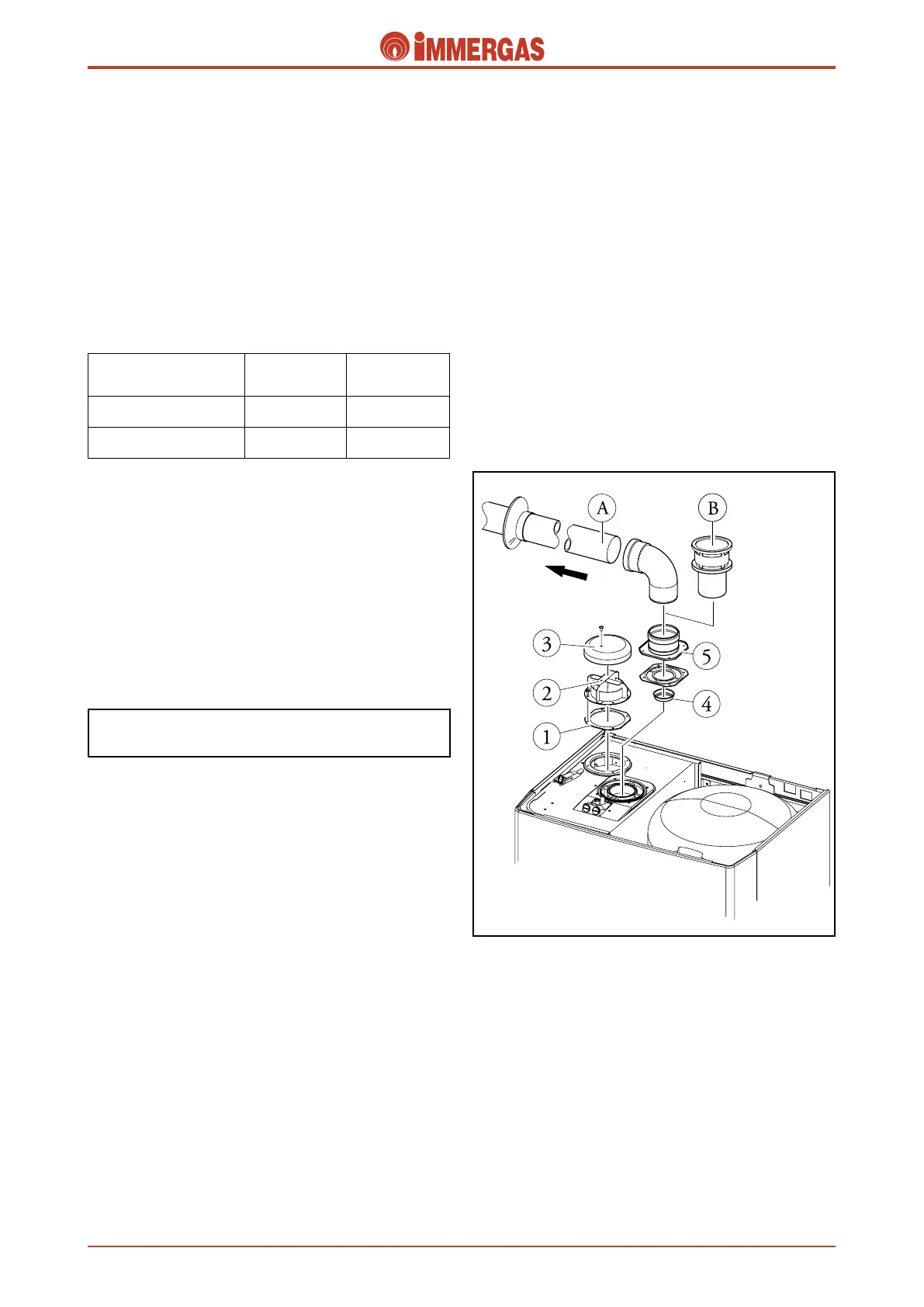
Extraction.
e air is aspirated exploiting the hole at the top of the air-
tight chamber and on which, after first fitting the seal (1),
the wind diverter (2) is mounted with the exhaust flange (3)
screwed on it.
Exhaust.
e flange used in split systems is used here to connect to the
80 mm diameter exhaust pipes.
By using the accessories you can have either a horizontal (A)
or vertical (B) exhaust type.
To ensure the boiler works correctly a 49 Ø (4) diaphragm
must be mounted between the exhaust coupling and the
flange (5).
To avoid condensation problems the exhaust pipe must be no
longer than 5 straight metres in the case of normal pipes
and 12 straight metres if they are insulated.
e maximum permitted length is 12 straight metres.
Airtight chamber fan-assisted configuration
(type C).
(See EOLO Maior @).
Extraction and exhaust kit.
(See EOLO Maior @).




 To Next Page