12
STZM@ ed 05/04 ZEUS Maior @
Technical DocumentationTechnical Documentation
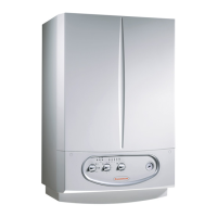
Flue circuit.
Operation.
e products of combustion, after hitting the water-gas ex-
changer (2), are conveyed to a hood (4) on top of which the
fumes extractor (5) is fitted (fan).
Fan operation ensures the forced expulsion of the fumes and,
at the same time, creates a vacuum in the airtight chamber (3)
so the combustion air can be aspirated from outside.
Correct fume extraction is controlled by a differential flue
pressure switch (6); when it trips it either enables or prevents
burner ignition.
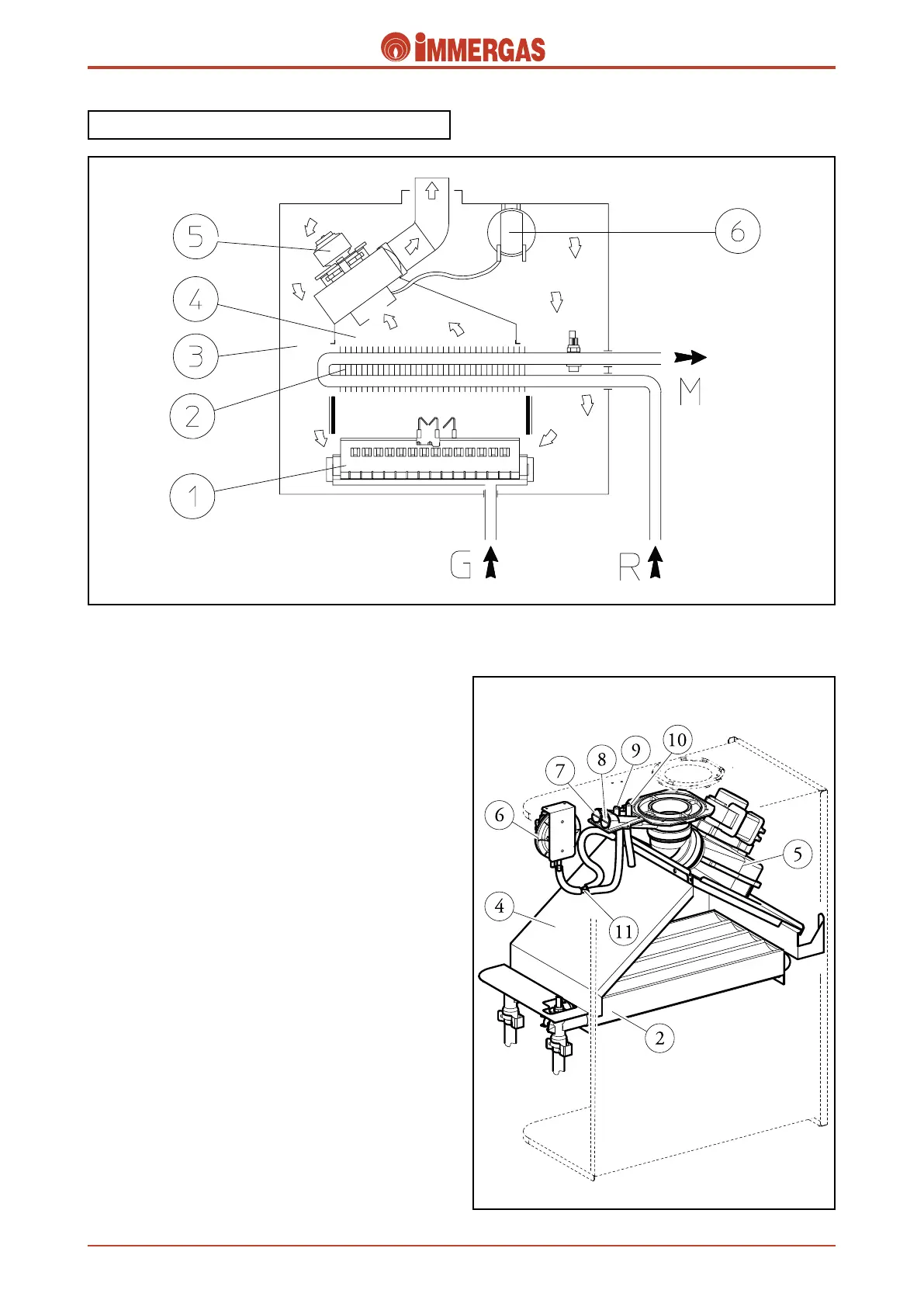
Air/fumes testing holes (7-8).
ere are two holes with screw closing on the top of the outside
of the airtight chamber which can be accessed from the front;
they are used to sample combustion air (7) and fumes (8).
Signal pressure points, flue pressure switch (9-
10).
ere are two pressure points with screw closing on the top
of the outside of the airtight chamber. e signal at the ends
of the flue pressure switch (6) can be measured by means of
these points.
e positive pressure point (10) is connected to the inside of
the airtight chamber.
Likewise, the negative pressure point (9) is coupled to a Y-
shaped pipe (11) that, in turn, is connected to the draught
diverter (4) and to the negative pressure point of the flue
pressure switch (6).
 Loading...