Chapter8 Communication Function
8-38
4) Example
-. Device M000 is increased by program per 1 second.
-. Writing M000 to output area P004 of slave
-. Reading slave’ s output area P004 to master’ s output area P009
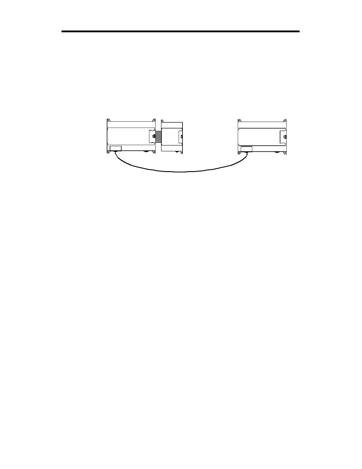
The following example uses the above diagram to explain the operation of K7 Base Unit.
-The data of the master K7 Base Unit is increased by INCP instruction and sent to be written on
the output contact point P04of the slave K7 Base Unit. And in return, the master K7 Base Unit
reads the data that is written on the output contact point of the slaveK7 to write them on the output
contact point of extended digital input/output module, G7E-DR10A.
K7 base unit
(Slave :
Station No. 31)
K7 base unit
(Master :
Station No. 0)
G7E-DR10A
1:1 built-in communication between K7's