iDrive2 inverters Installation Guidelines
14
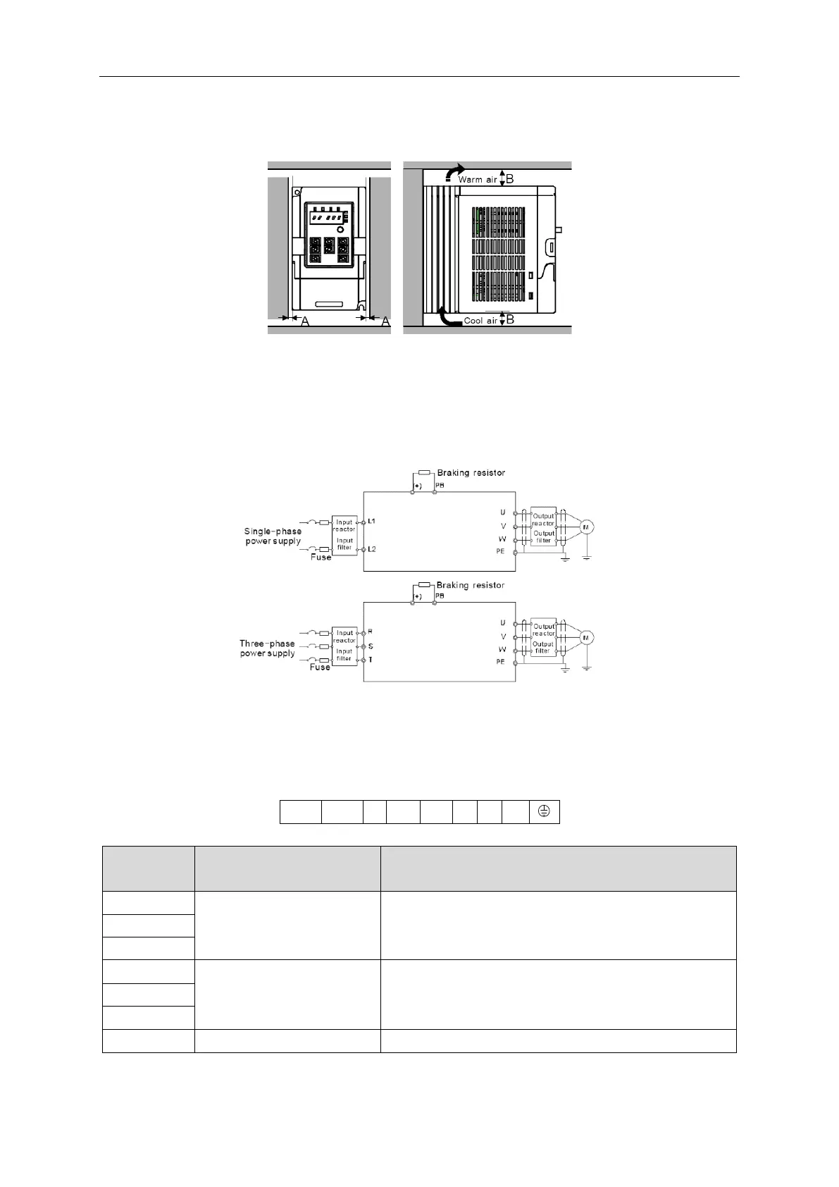
3.1.4 Installation space
Fig 3-2 Installation space
Note: Fan cooled drives can be mounted side by side, natural cooled drives require 30mm clearance (Dim A)
A minimum clearance of 100mm is required above and below the drive (Dim B).
3.2 Standard wiring
3.2.1 Connection diagram of main circuit
Diagram 3-3 Connection diagram of main circuit
Note:
The fuse, DC reactor, braking resistor, input reactor, input filter, output reactor, output filter are optional
parts. Please refer to Peripheral Optional Parts for detailed information.
3.2.2 Terminals figure of main circuit
Fig 3-4 Terminals of main circuit
Power input of the main circuit
3-phase/1-phase AC input terminals are generally connected
to the incoming supply.
3-phase AC output terminals are generally connected to the
motor.
Braking resistor terminal
PB and (+) are connected to an external resistor.