iDrive2 inverters Appendix A Technical data
84
Appendix A Technical data
A.1 Ratings
A.1.1 Capacity
Inverter sizing is based on the rated motor current and power. To achieve the rated motor power reference in the
table, the rated current of the inverter must be higher than or equal to the rated motor current. Also the rated power
of the inverter must be higher than or equal to the rated motor power. The power ratings are the same regardless
of the supply voltage within one voltage range.
Note:
1. The maximum allowed motor shaft power is limited to 1.5*PN. If the limit is exceeded, motor torque and current
are automatically restricted. The function protects the input bridge of the drive against overload.
2. The ratings apply at ambient temperature of 40 °C
3. It is important to check that in Common DC systems the power flowing through the common DC connection
does not exceed PN.
A.1.2 Derating
The load capacity decreases if the installation site ambient temperature exceeds 40 °C, the altitude exceeds 1000
meters or the switching frequency is changed from 4 kHz to 8 kHz.
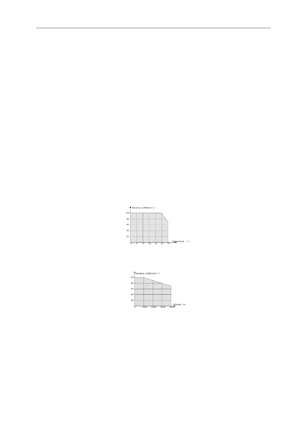
A.1.2.1 Temperature derating
In the temperature range +40 °C~+50 °C, the rated output current is decreased by 3% for every additional 1 °C.
Refer to the below list for the actual derating.
A.1.2.2 Altitude derating
The device can output at rated power if the installation site below 1000m. The output power decreases if the
altitude exceeds 1000 meters. Below is the detailed decreasing range of the derating:
A.1.2.3 De-rating of the carrier frequency
The setting range of carrier frequency in different power rating is different. The rated power is defined as its factory
carrier frequency. The inverter has to derate 20% for every additional 1 KHz carrier frequency if the carrier
frequency exceeds the factory value.
A.2 CE
A.2.1 CE mark
The CE mark is attached to the drive to verify that the drive follows the provisions of the European Low Voltage
(2006/95/EC) and EMC Directives (2004/108/EC).