iDrive2 inverters Keypad Operation Procedure
18
4 Keypad Operation Procedure
The keypad is used to control iDrive2 XKL series inverters, display active data and adjust parameters.
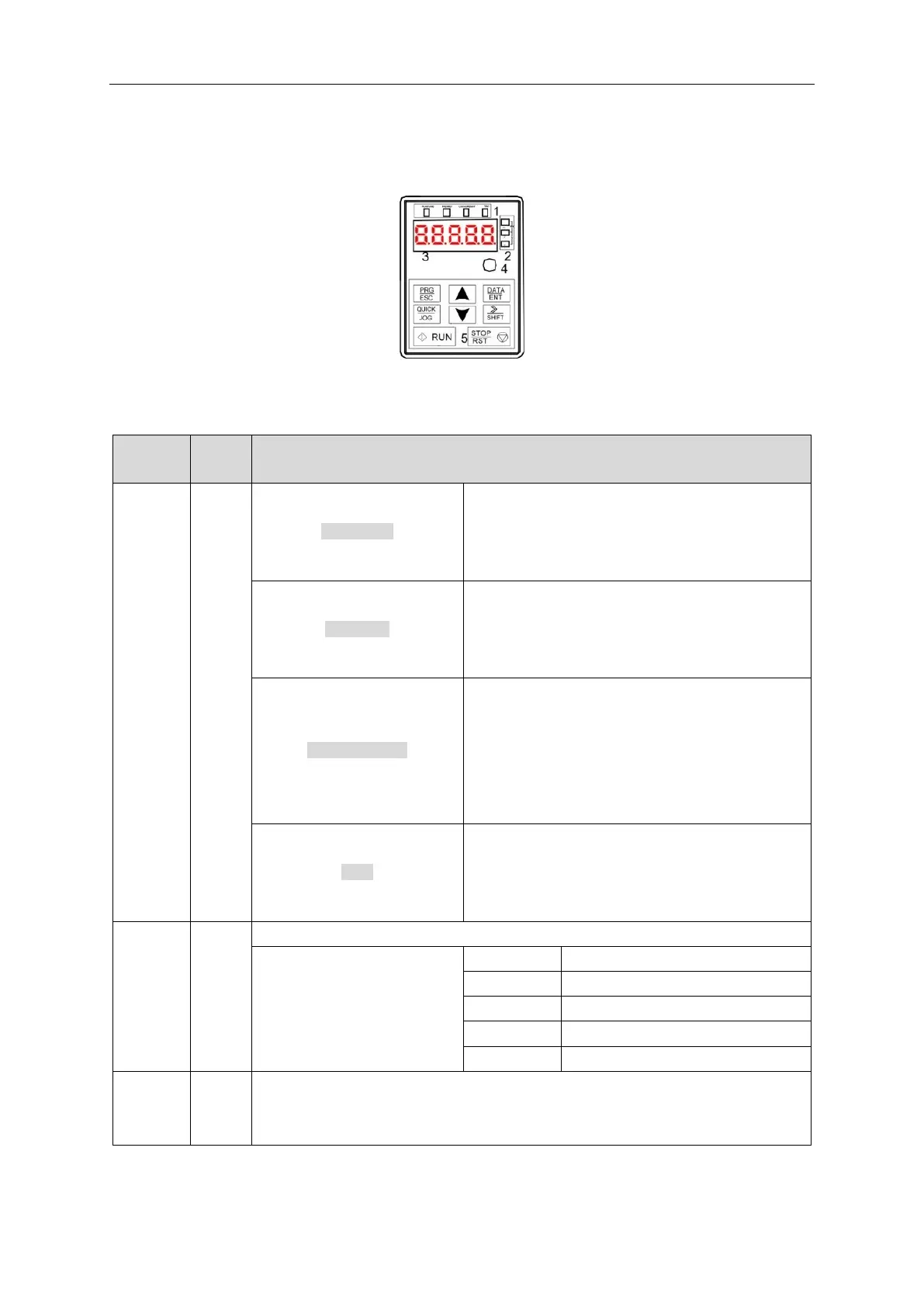
Fig 4-1 Keypad
Note: Fix the external keypad with M3 screws or the installation bracket. The installation bracket is
optional.
LED off means that the inverter is in stopped state;
LED flashing means the inverter is in parameter
autotune state; LED on means the inverter is in running
state.
LED off means the inverter is in forward rotation state;
LED on means the inverter is in reverse rotation state
LED for keypad operation, terminals operation and
remote communication control.
LED off means that the inverter is in keypad control;
LED flashing means the inverter is in terminal control;
LED on means the inverter is in communication
control.
LED on when the inverter is in fault state; LED off in
normal state; LED flashing means the inverter is in
overload pre-alarm state.
Signifies the current unit type being displayed.
5-digit LED display displays various monitoring data and alarm code such as set
frequency and output frequency.