Programmable controller PI 6000
29
3.4 Maintenance
Attention during pyrometer services or programming at the PI 6000:
Should the instruments be integrated in a running machine process the machine has to be switched off and
secured against restart before servicing the pyrometer.
4 Mechanical installation
4.1 Assembling
A front panel cut-out of 45
+0.6
x 92
+0.8
mm is required to fit the PI 6000. A depth of at least 165 mm is required
to fit the unit. Screw clips provided are used to fasten the unit after fitting in the mounting opening.
5 Electrical installation
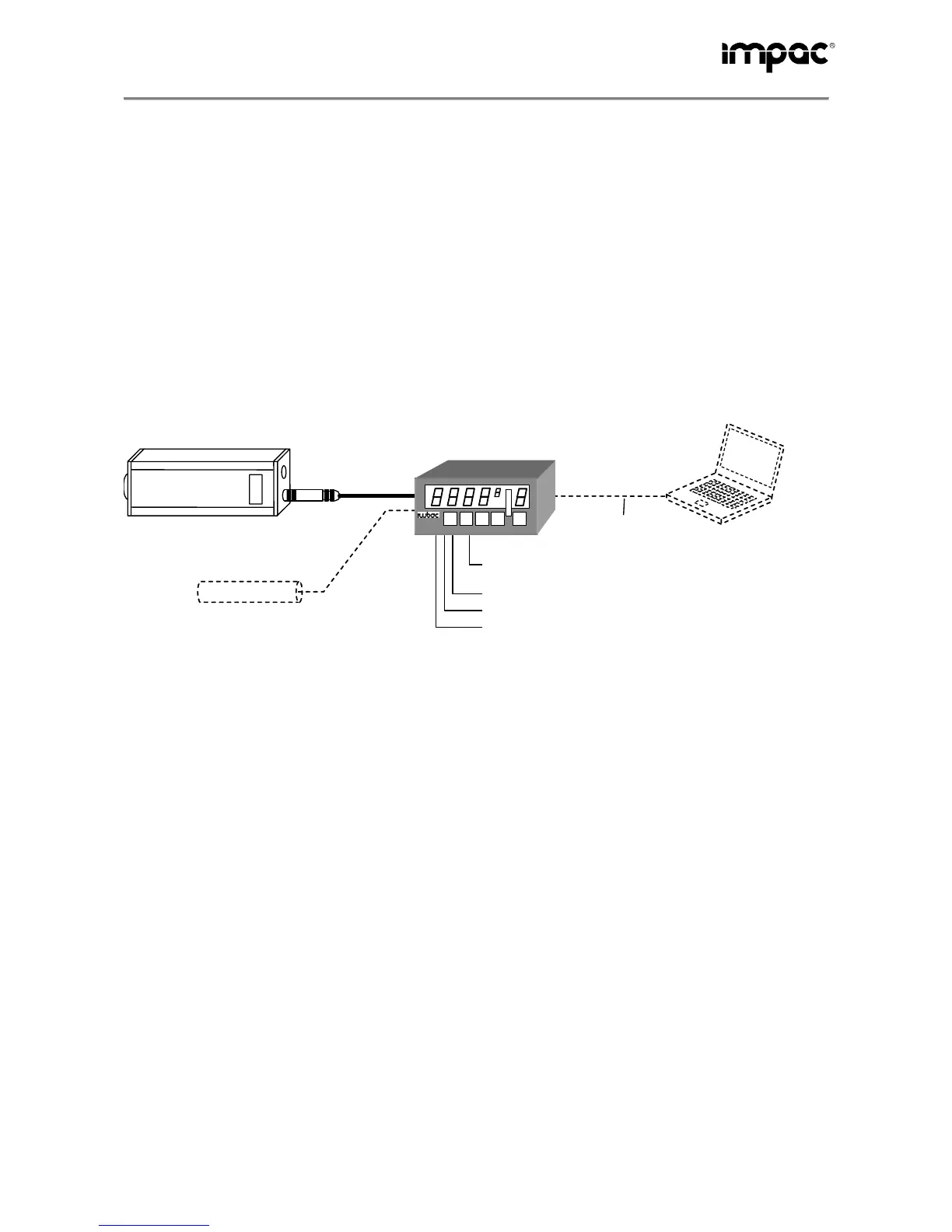
5.1 Overview
Digital measurement pyrometer
(connection using analogue output
and RS232 or RS485 interface)
larm pyrometer
(optional)
Interface cable to the
PC (RS232)
PC for
programming
Power supply for PI 6000
and pyrometer
PI 6000
Control output
Switched outputs
Remote start / -stop
PI 6000
Measurement pyrometer: An IMPAC digital pyrometer with an analogue output is required as the trans-
ducer. The interface is used for PI 6000 communication with the pyrometer, the analogue output for the fast
transfer of the measured value. The correct selection of the pyrometer depends on the material from which
the measured object is made and the measurement task.
PC / PLC: A PLC or a PC with the Windows operating system and the InfraWin software (included with the
items supplied) are required for programming. As an alternative, programming can be undertaken with the
aid of the UPP
®
table (see also 8, UPP
®
data format). The PC or PLC is connected using an RS232 inter-
face.
Alarm pyrometer: A second pyrometer can be connected in addition to the measurement pyrometer; the
second pyrometer is used for monitoring the measured object or the measurement task. If an adjustable
maximum temperature is exceeded, a "safety shut-down" switched output (semiconductor relay) is switched.
Any pyrometer suitable for the measured object and that has an analogue output 0 ... 20 mA or 4 ... 20 mA
and positive measuring range limits can be used as the alarm pyrometer.
Switched outputs: 3 further switched outputs (semiconductor relays) such as “program start“, “generator
on“ and “ready“ can be used for monitoring the program or external control.
Remote start / stop: A button can be connected for remotely starting or stopping the control program cur-
rently selected.
Control output: The analogue control output can be set to 0 ... 20 mA or 4... 20 mA.