Specications 15 Crane Reference
4004i - Manual # 99904386
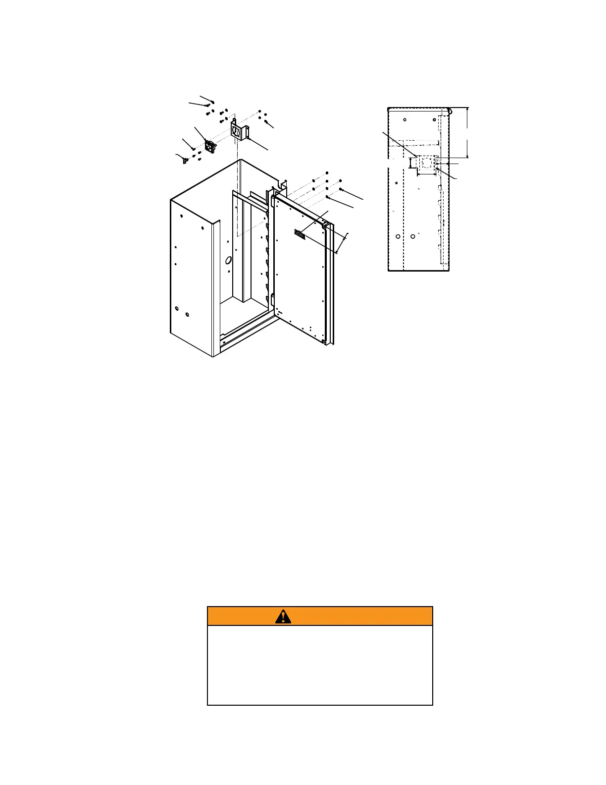
CRANE INSTALLATION - CONTINUED
3. Install the vehicle level indicator (item #8) parallel to the door reinforcements.
4. After mounting your crane, wire the crane to the vehicle’s 12VDC electrical system using the following steps.
Use the parts list above to identify parts. Your crane installation kit, 51721572, includes a 10.7 m (35’) long
cable, IMT # 89044276 (item #13 in the parts list). Approximately 7.6 m (25’) of this cable is required to
connect the crane power switch to the vehicle battery, and the rest of the cable is used for ground connec-
tions between the crane, vehicle battery, auxiliary battery, and chassis ground. Cut the cable to length after
determining the lengths required.
5. Ground the crane by connecting the crane ground cable to bare metal inside the crane box.
6. Connect the crane power cable from the male power cable connector to the power switch. Connect cable
(item #13 - 89044276), cut to length, from the crane power switch (item #7) to the fuse. Use 3/8” (0.95 cm)
ring terminal (item #9 - 77040209) for each connection. Heat shrink the connections (item #4 - 89392333).
7
8
21
6
18
19
6
20
22
22
LOCATION OF
SWITCH BRACKET
IN CRANE BOX
4 HOLES,
0.266" DIA.
3.5"
5.03"
2.75"
13.5"
INSIDE VIEW
OF CRANE BOX
KEY SUPPLIED
WITH 70734331
SWITCH. SPARE
KEY - 70734357.
WARNING
Protect the power cable from damage by
fastening it inside the frame channel and
covering it with protective covering including
loom, conduit, etc. Be sure to use rubber
grommets or other protection when running
the power cable through steel bulkheads.

 Loading...


