If the installation dimension is not correct, turn the base body forward or
backward, until the setting dimension is achieved. Observe the installation
position.
7.
Example: Close TOPlus on cooling lubricant device through main spindle
X
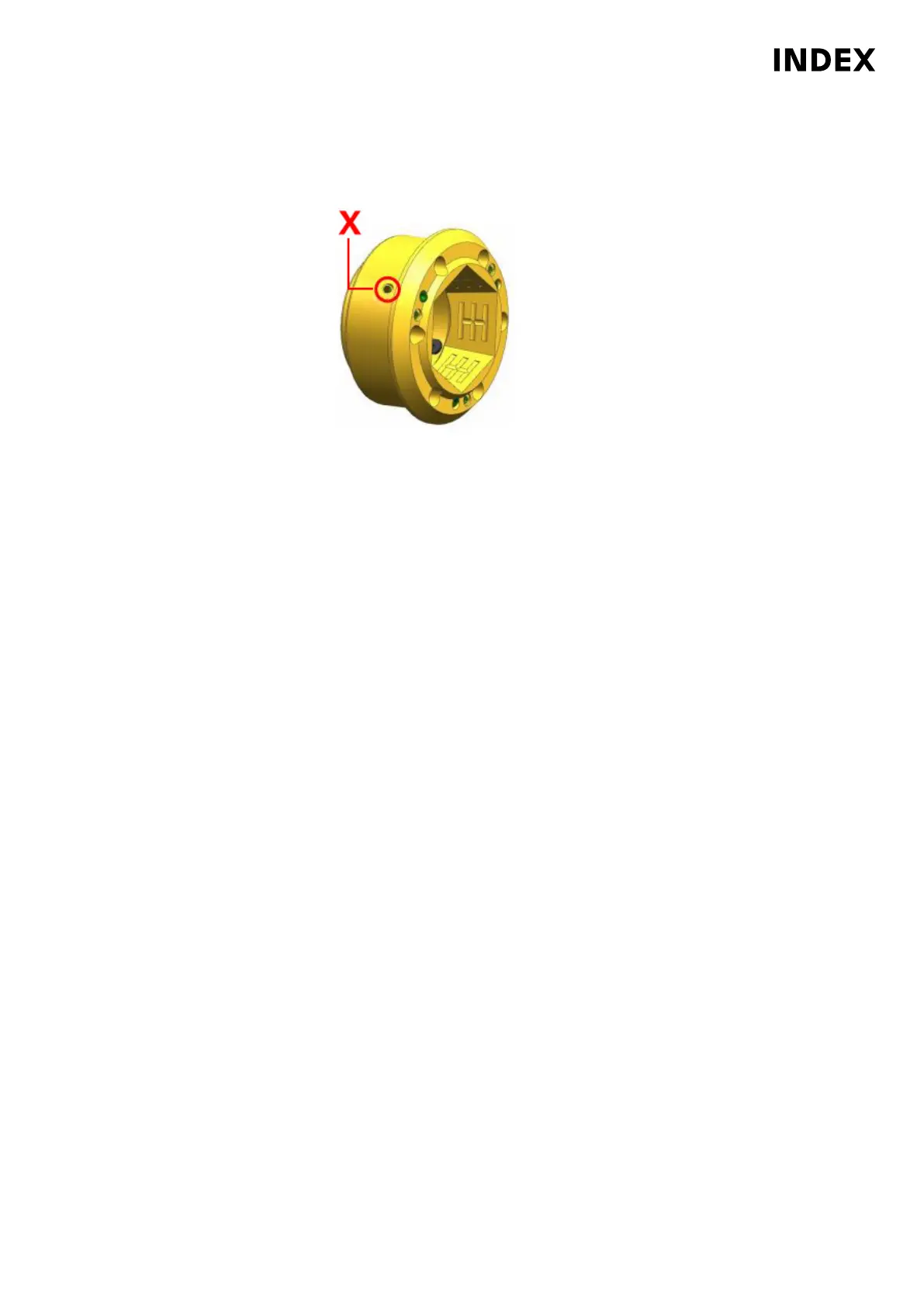
Bonded (Loctite
®
221) set screw
Check the clamping element holder. Valid for all machines MS32-6.3, MS40-6
and MS40-8 with TOPlus clamping system, robot and cooling lubricant device
through the main spindle. Before reinstalling the clamping element holder,
make absolutely sure that the holes marked X are closed with set screws. The
set screws must be screwed down to the bottom of the hole and bonded with
Loctite
®
221.
8. Place the clamping element holder (2) on the spindle nose face (5) and screw
in 6 screws.
9. Tighten the 6 screws (3) crosswise to a torque of 14.9 Nm.
10. Insert collet (4).
11. Be sure to remove the spindle lock (device/locking pin) after finishing
the work.
Maintenance Summary - Care activities
43
Maintenance Instructions
MS40-8
DIM078EN - 02.06.2020