IDS 410/422 User's Manual
47
DIAGNOSTIC TESTS
The DIAGNOSTIC TESTS are accessed using configuration function 69. Hold the
GROSS/NET key down and press the UNITS key to enter configure mode. The display prompts
"CFG xx" where xx is the currently selected parameter. Enter 69 and press the ENTER key to
access the DIAGNOSTIC TESTS.
The display prompts "diA xx" where xx is the last selected diagnostic function. Select a test
number from the table below. Enter the test number and press the ENTER key.
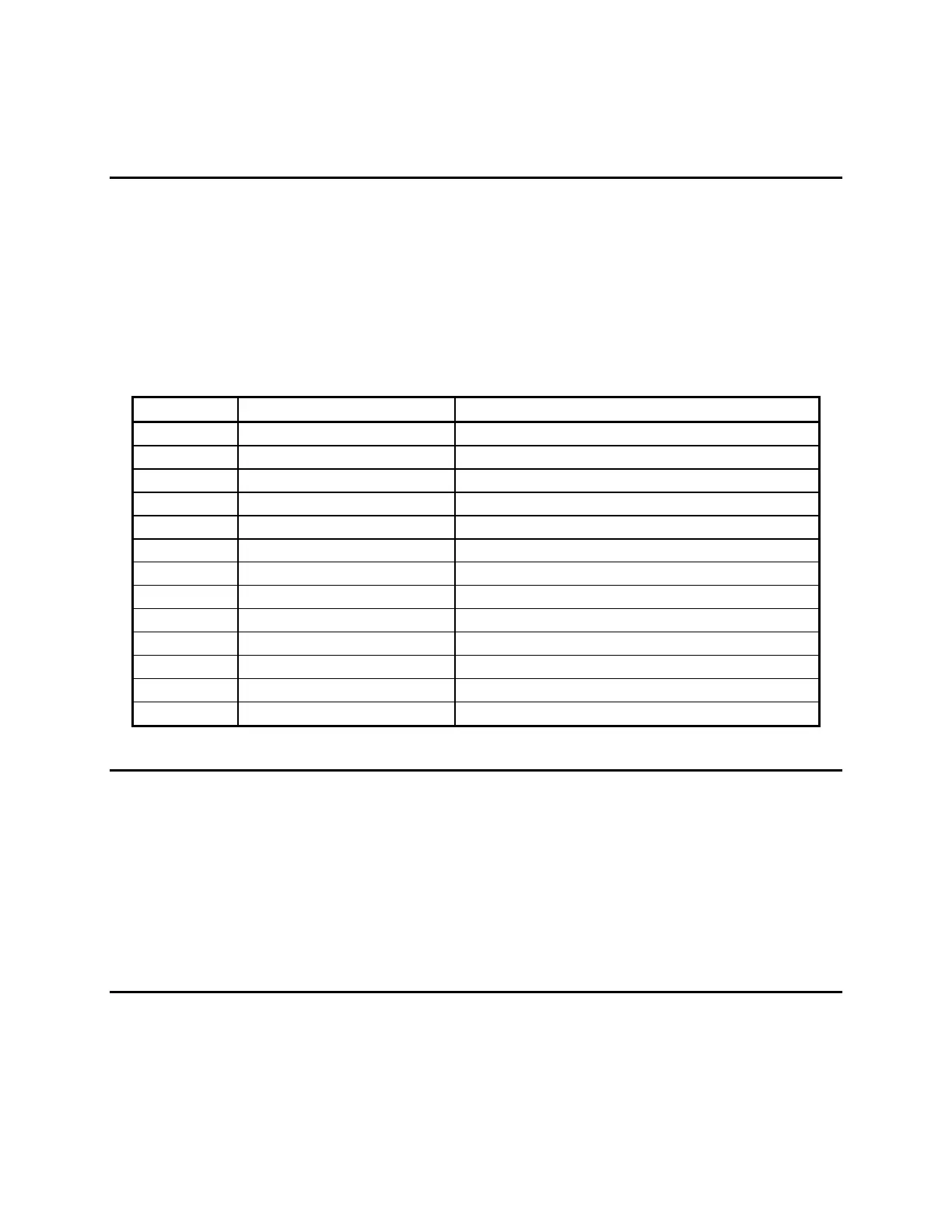
Table of Diagnostic Tests
Test No. Hardware Tested Description
1 Serial Com. Port 1 Display input data.
2 Serial Com. Port 1 Display input error count.
3 Serial Com. Port 1 Transmit data.
4 Serial Com. Port 2 Display input data.
5 Serial Com. Port 2 Display input error count.
6 Serial Com. Port 2 Transmit data.
7 TTL I/O 1,2 &3. Activate TTL out / in
8 A/D converter Display raw conversion data.
9 Ram Memory Test memory for errors.
10 Display Turn on all LED’s and display segments.
11 EAROM data Print the EAROM configuration data.
12 Serial Com. Port 1 Transmit/Receive loop-back test.
13 Serial Com. Port 2 Transmit/Receive loop-back test.
Diagnostic Test 1: Serial Com Port 1 - Display Input Data
This test displays serial data as it is received by serial communications port 1. The numeric
display has limited alpha display capability, however numeric and some alpha characters are
legible. If all data being received is unintelligible, the baud rate is probably incorrect. If nothing
is displayed on the display, then check the following:
1. RS232/Current switch on the main circuit board.
2. Cabling between the communicating units.
3. Make sure the sending unit is actually sending data.
Diagnostic Test 2: Serial Com Port 1 – Display Errors
This test displays the number of framing and parity errors that are detected in the input data
stream. The the error count is set to zero when entering this test. New errors are displayed as
"PxxFxx" where Pxx is the number of parity errors and Fxx is the number of framing errors. If
the error count exceeds 99, the display will remain at 99.