24 Installation
Anti-intrusion control panels
•Cable type
The cable section used affects the dispersion of the conductor signals.
• Communication speed over the BUS
This parameter can be changed using the Prime/Studio software (38.4, 125 or 250kbs).
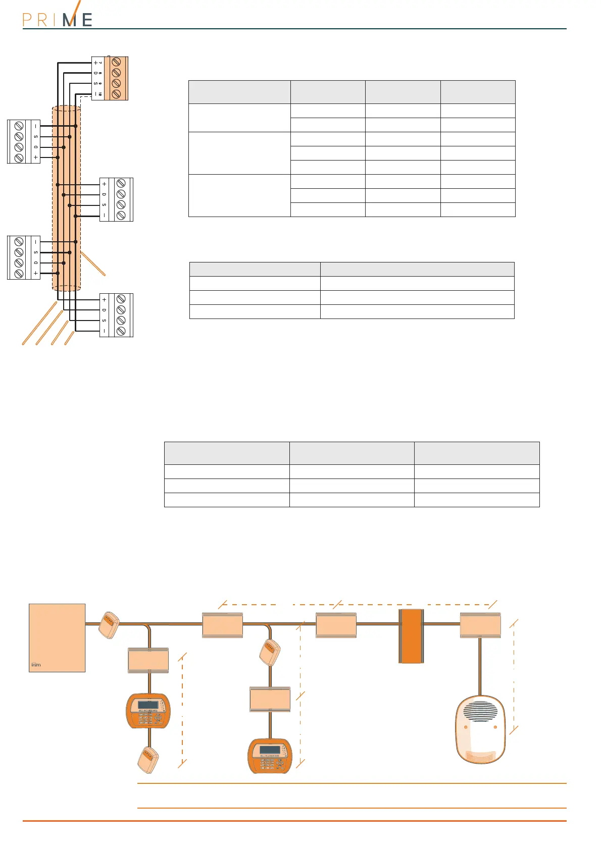
• Number and distribution of IB200 isolators.
To increase the reliability and the extension of the BUS, it is necessary to use isolators.
For proper installation of the isolator, and therefore of the BUS, it is necessary to size the BUS
branch in which the isolator is located based on the number of peripherals connected to the
branch and their total current absorption. This absorption is therefore to be compared with the
“Maximum absorption from the control panel” data.
Another feature is the length of the line that is downstream of the isolator up to the
successive isolator or EOL. Following is a table with indicative values of the length depending
on the BUS speed:
The lengths (L) shown here can be identified with:
• the length of the cables between an isolator and the successive peripherals or, in the case
of a single line, between two successive isolators.
• the sum of the lengths of all the lines that start from an isolator and arrive at successive
isolators or, in the case of branched lines, ending with peripherals.
For this purpose, we provide an example for a system with a BUS speed of 125kbps:
Note
The distances indicated in the tables are obtained under optimal wiring conditions and in respect of the
points indicated above.
Table 3-1: Recommended cable
Cable
AF CEI 20-22 II
n. wires
Section (mm
2
)
I-BUS terminal
4 wire cable + shield
20.5+ -
20.22D S
6 wire cable + shield
20.5+ -
20.22D S
2 0.22 available
6 wire cable + shield
20.75+ -
20.22D S
2 0.22 available
Table 3-2: BUS sizing
BUS speed Maximum admissible length of the BUS
38.4kbps 1000m
125kbps 700m
250kbps 300m
Table 3-3: Sizing of IB200 isolators
BUS speed
Cable length downstream of
the isolator (L)
Maximum number of cas-
caded isolators
38.4kbps 500m 9
125kbps 350m 6
250kbps 200m 2
Control panel
IB200
IB200
BUS branch
1 isolator in
cascade
connection
IB200
BUS branch
2 isolators in
cascade
connection
BUS branch
3 isolators in
cascade
connection
IB200
IB200
l
2
l
1,
l
4,
l
5,
l
6 < L
l
2 +
l
3 < L
l
1
l
6
l
4
l
3
l
5