Installation manual
Installation 25
It is not recommended to position an isolator immediately after the control panel Each isolator
should be positioned in the points where the quality of the BUS drops drastically.
3-3
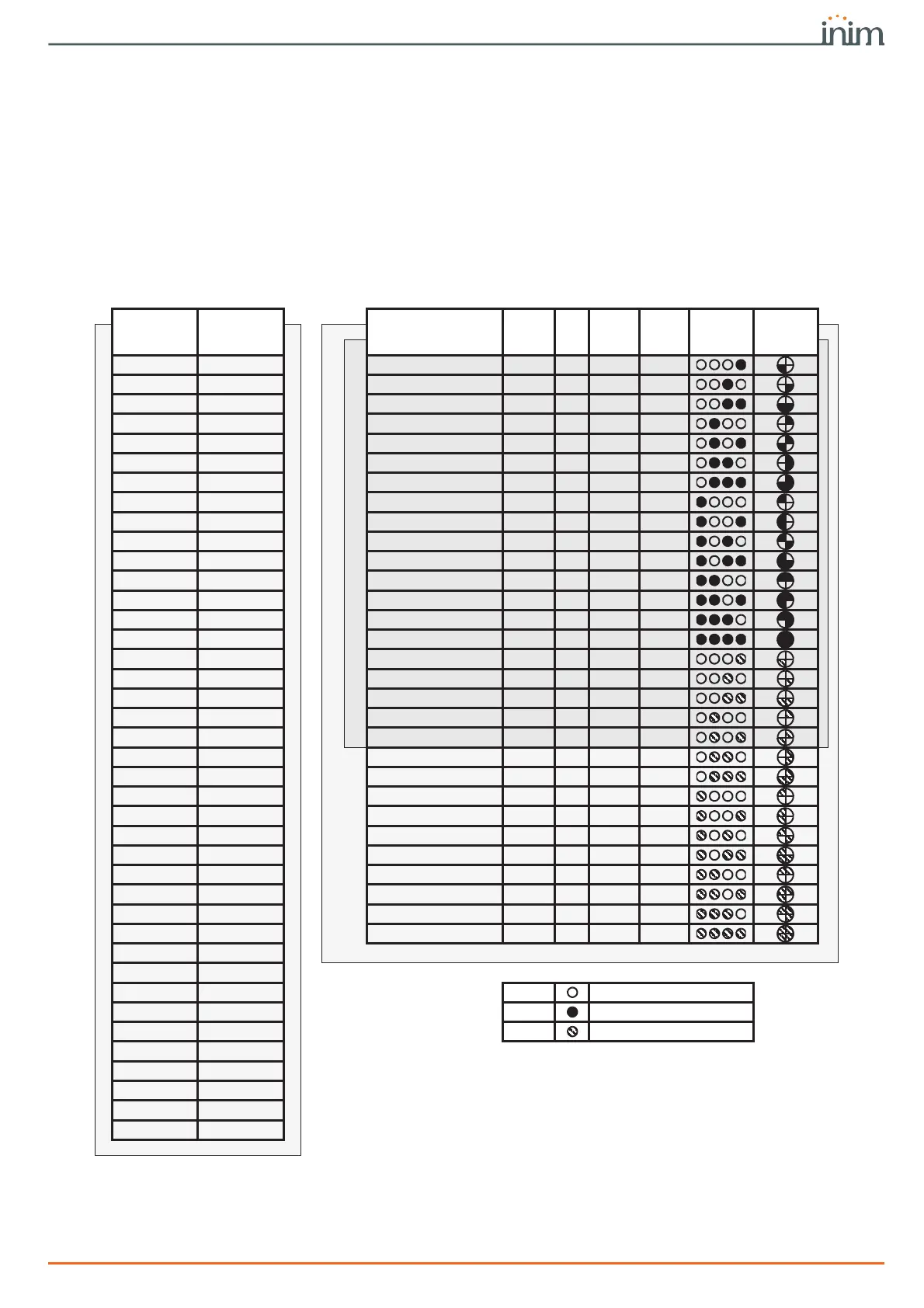
Addressing the peripherals
In order to allow the control panel to identify the peripherals distinctly, you must assign a
different address to each device. It is possible for two peripherals of different types to have
the same address (for example address 3 for a Flex5 and also for a Joy keypad), while two
peripherals of the same type must never have the same address.
Depending on the type of control panel installed, each type of peripheral has a maximum
number of addresses that must not be exceeded. The following table shows the available
peripheral addresses and the maximum number of addresses allowed.
Table 3-4: Peripherals address
Expansions
address
DIP-switch
12345678
Expansions and
transceivers
address
Red
Blu
e
Green
Yel-
low
nBy/S
BS200
nBy/X
nBy/K
Prime120L, Prime240L and Prime500L
1 00000000
Prime060S, Prime060L
1 0 0 0 1
2 00000001 2 0 0 1 0
3 00000010 3 0 0 1 1
4 00000011 4 0 1 0 0
5 00000100 5 0 1 0 1
6 00000101 6 0 1 1 0
7 00000110 7 0 1 1 1
8 00000111 8 1 0 0 0
9 00001000 9 1 0 0 1
10 00001001 10 1 0 1 0
11 00001010 11 1 0 1 1
12 00001011 12 1 1 0 0
13 00001100 13 1 1 0 1
14 00001101 14 1 1 1 0
15 00001110 15 1 1 1 1
16 00001111 16 0 0 0 L
17 00010000 17 0 0 L 0
18 00010001 18 0 0 L L
19 00010010 19 0 L 0 0
20 00010011 20 0 L 0 L
21 00010100 21 0 L L 0
22 00010101 22 0 L L L
23 00010110 23 L 0 0 0
24 00010111 24 L 0 0 L
25 00011000 25 L 0 L 0
26 00011001 26 L 0 L L
27 00011010 27 L L 0 0
28 00011011 28 L L 0 L
29 00011100 29 L L L 0
30 00011101 30 L L L L
31 00011110
32 00011111
33 00100000 0LED Off
34 00100001 1LED On
35 00100010 L Flashing LED
36 00100011
37 00100100
38 00100101
39 00100110
40 00100111