30 Installation
Anti-intrusion control panels
3-6-2
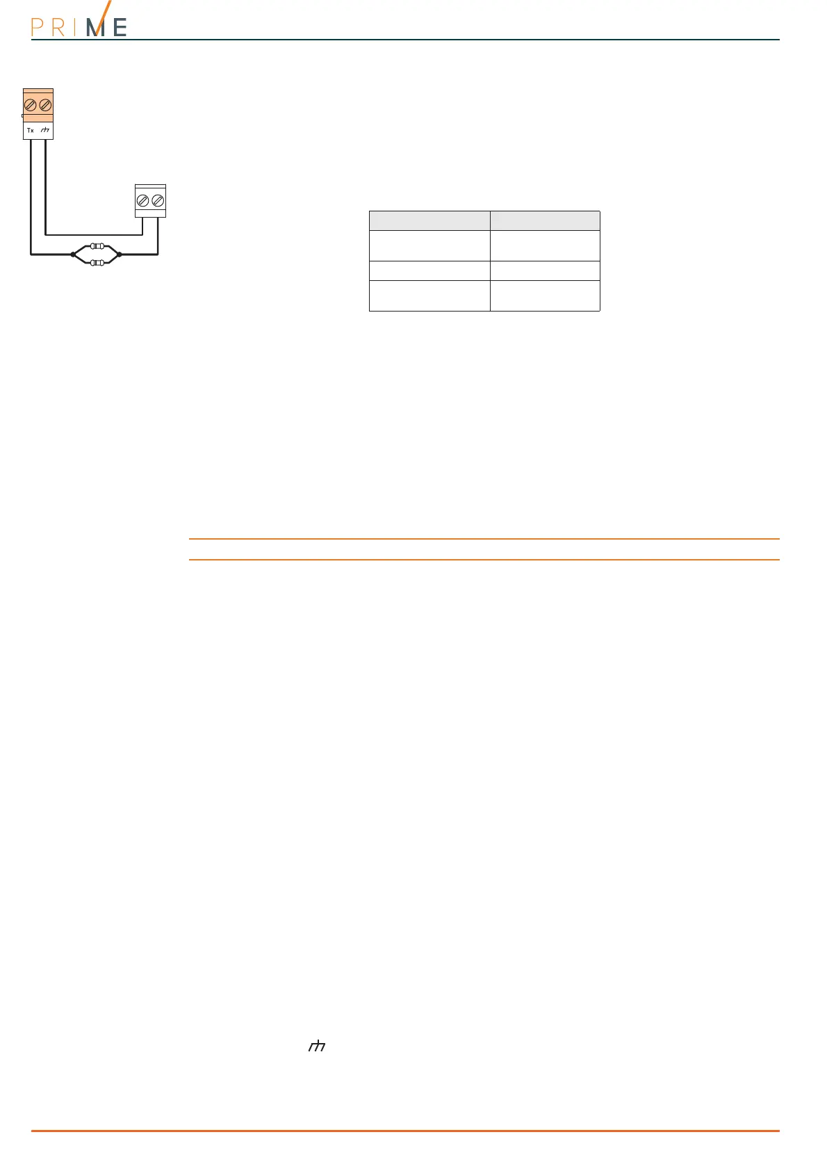
Single balancing (N.C. with EOL)
In this case, the discriminated conditions are:
•stand-by
•alarm
• tamper (wire cutting)
• tamper (short-circuit)
For each of these, the control panel reads different resistance values on the terminal, shown
below in Ohm.
The alarm condition is detected exclusively by the pulse count and sensitivity, in accordance
with the programmed parameters (refer to the Programming manual paragraph 6-1 Zone/
Ingressi, Roller-blind/Shock).
3-7
Learn zone balancing
After connecting and balancing all the zones, the installer can start the auto-enrolling phase of
balancing value, thus avoiding the manual setting of each individual balancing value (refer to
the Programming manual, Chapter 17, Parametri di fabbrica, Learn zone bal.).
Note
The Self-balancing feature is a Registered patent.
3-8
Connecting outputs
In correspondence with any event recognized by the control panel it is possible to activate one
(or more outputs).
For the connection of the outputs to terminals T1 and T2 of the Air2-MC300 device, refer to
the Installation Manual supplied with the Air2-BS200.
3-8-1
Connecting sounders/flashers
In the event of an intrusion alarm, the control panel will activate the output which is
connected to the audible/visual signalling devices. The most commonly used alarm output to
drive a self-powered sounder/flasher is the relay output on board the control panel.
The following wiring diagram shows the connection of a self-powered sounder/flasher (in this
case the IVY sounder/flasher manufactured by INIM) and an indoor sounder/flasher.
3-8-2
Connection of open-collector outputs
With the exception of the relay output, all the control panel and Flex5/P and Flex5/U outputs
are “open collector” outputs:
• OC1 and OC2 are open collector outputs capable of driving maximum currents in
accordance with the Table 2-1: Control panels - electrical and mechanical features.
• All the terminals configurable as outputs are open-collector outputs capable of driving a
maximum current of 150mA.
Following you will find examples of typical connections for the activation of a load when
closing to ground ( ) a Normally Open output.
Ohm Zone
> 3900 / 2
tamper (wire cut-
ting)
3900 / 2 stand-by
0
tamper (short-cir-
cuit)