Installation manual
Installation 27
3-5
Wiring and balancing alarm
detectors
The wiring and respective balancing method depend on the type of detector you are installing,
and the level of protection you wish to achieve. The detectors can be powered through:
• terminals [+AUX/12V] and [-/GND] on the control panel
• terminals [+AUX/12V] and [-/GND] on FLEX5 expansions
• terminal [+/12V] and terminals [-/GND] on keypads
• from any 12V ancillary source on condition that its GND reference is in common with that
of the control panel.
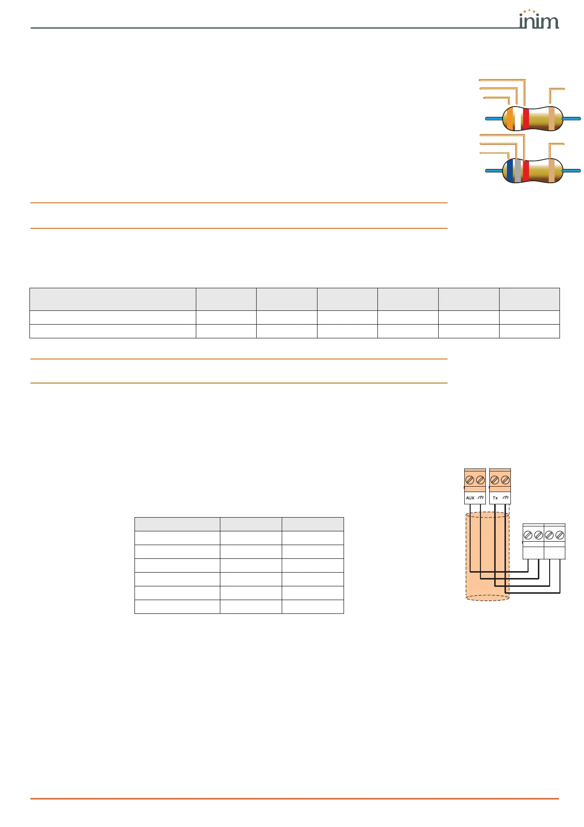
The resistors used for balancing are:
•• 3K9Ohm 1/4W
•• 6K8Ohm 1/4W
ATTENTION!
The resistors used must be connected directly to the detector terminals, never to the
terminals of the control panel or peripherals.
The following table indicates the protection level of each detector type and the balancing
options provided by the control panel:
Note
Single balancing provides the same level of protection as Double balancing, when the tamper contact of
the detector is connected to a balanced zone on the control panel.
3-5-1
N.C./N.O. balancing
In cases of N.C. balancing (normally closed) and N.O. balancing (normally open), it is possible
to detect two distinct zone conditions:
•stand-by
•alarm
For each of these, the control panel reads different resistance values on the terminal, shown
below in Ohm.
If you wish the detector to signal tamper events, connect the detector “Tamper” terminal to a
“24h” zone on the control panel.
Red
White
Gold
Red
Grey
Blue
Gold
3K9 Ohm
1/4W
6K8 Ohm
1/4W
Table 3-5: Protection level
BALANCING N.O. N.C. Single Double Double zone
Double zone
with EOL
PIR or Dual technology
very low low medium high medium high
Magnetic contact
very low low medium / medium high
Ohm N.C. N.O.
> 2 x 3900 + 6800 alarm stand-by
> 2 x 3900 + 6800 alarm stand-by
3900 + 6800 alarm alarm
2 x 3900 alarm alarm
3900 stand-by alarm
0stand-byalarm
Alarm
+12V GND

 Loading...


