Installation manual
Installation 23
• Does not require user-code entry to access the sections which correspond to the “Settings”
button.
• The first parameters shown in the “Settings - Alien” section are the addresses of the Alien
keypad and its integrated proximity reader and, only for the Alien/S, the status of tamper
enablement on the keypad.
• It is not possible to access the “Climate” section.
• The display shows the address of the Alien keypad and its integrated proximity reader in
the top left-hand corner of the home page.
• The display shows the characters relating to the operating status of the partitions in the
bottom left-hand corner of the home page.
The control panel can be placed in maintenance mode by:
• Inserting the Maintenance jumper in the “SERV” position.
• Enabling the “Maintenance” option
USING THE
MAINTENANCE
JUMPER
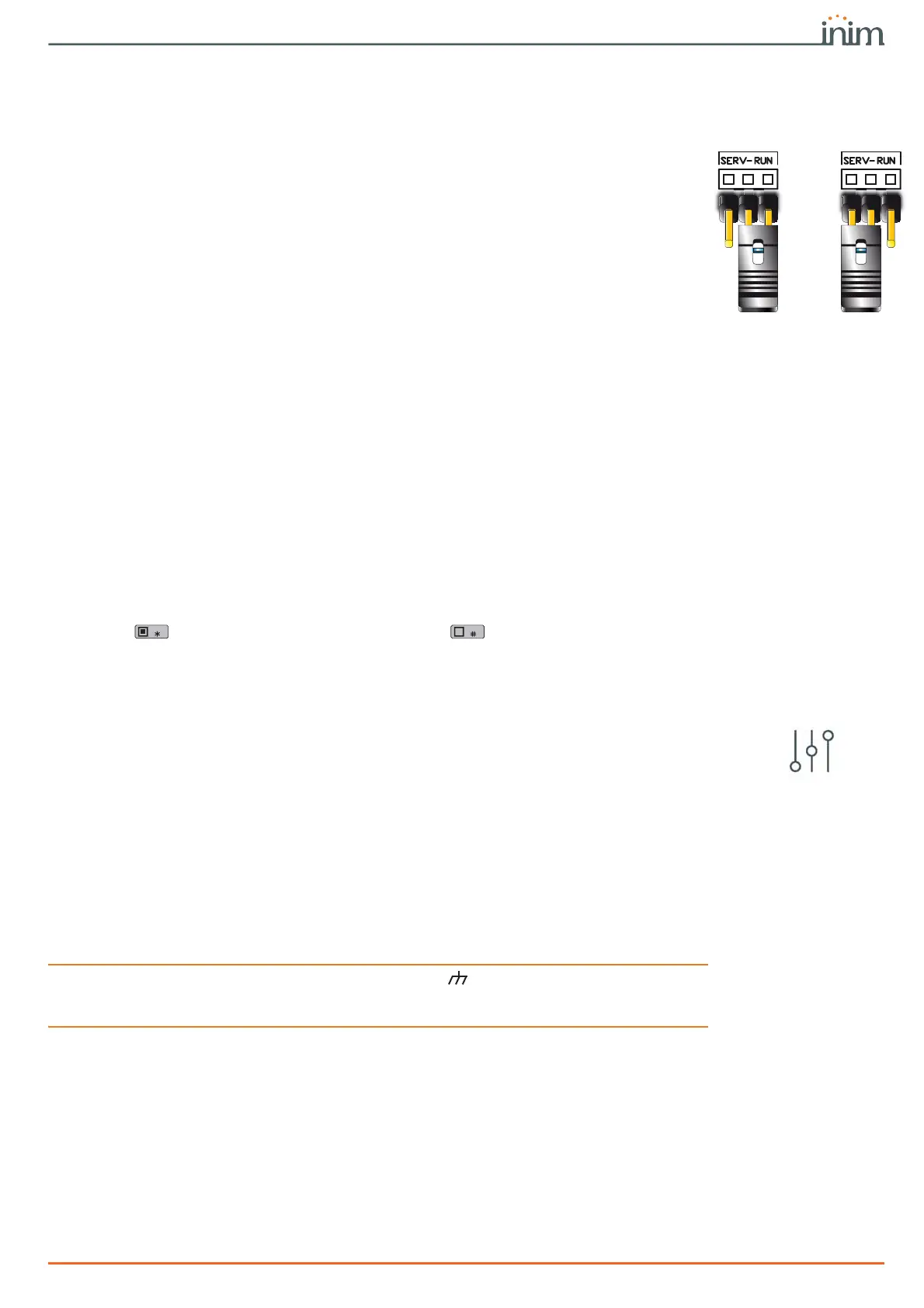
The Maintenance jumper (Table 2-6: Mother board - description of parts, I) can be inserted in
two different positions:
• “RUN” - control panel operating normally
• “SERV” - control panel ready for maintenance work
THE
“MAINTENANCE”
OPTION
The control panel enters “Maintenance” mode when this option is enabled and exits
“Maintenance” mode when it is disabled. You can enable/disable this option at the keypad or
via computer.
Via keypad1. Access the “Programming Panel options” section.
Type-in Code
(Installer PIN)
, PROGRAMMING Panel options
2. Press to enable the “Maintenance” option, or to disable it.
3. Press
OK to exit and save.
Via softwareThis option is made available by clicking on the Control panel parameters button in the
section on the left. The “Control panel parameters” section provides the “Maintenance” option,
click on this option to enable/disable it.
3-2
Installing peripherals
3-2-1
Connecting to the I-BUS line
The peripheral devices of the Prime system must be connected to the control panel via the I-
BUS.
The connection between the control panel and its peripherals is achieved through a shielded 4
wire (or more) cable.
ATTENTION!
The shield must be connected to one of the terminals (Negative or GND) at the control
panel end only, and must run along the BUS without being connected to negative or GND at
any other point.
The control panel connection is done using terminals “+ D S -” on the motherboard (Table 2-
7: Mother board - terminal board, 7-8-9-10).
SIZING
The sizing of the I-BUS line, i.e. the distribution of peripherals and the use of cables to connect
them, must be done on the basis of various project factors, in order to ensure the diffusion of the
signals of conductors “
D
” and “
S
” and the power supplied by conductors “
+
” and “
-
”.
The factors are:
• The current absorption of the connected devices.
In the case of insufficient power supply from the BUS line to peripherals and detectors, this
can also be supplied by external power supplies.
“RUN” position
“SERV”
position

 Loading...


