-99-
Introduction
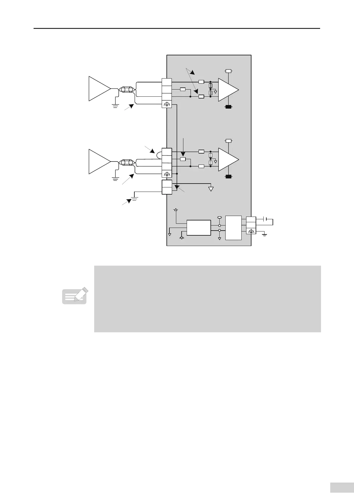
6) External wiring
7
7
L
Ē
L
Ē
(/%
4IJFMEFEMBZFSHSPVOEJOH
7
7
*
7
7
L
Ē
L
Ē
(/%
4IJFMEFEMBZFSHSPVOEJOH
7
7
*
Ē
"(/%
"(/%
'(
B
7PMUBHFJOQVU
C
$VSSFOUJOQVU
7
$0.
7
7
7
%$%$
DPOWFSUFS
'JMUFS
7%$
FYUFSOBM
QPXFS
"(/%
"(/%
*OQVUJNQFEBODF
*OQVUJNQFEBODF
.BOEBUPSZ
DPOOFDUJPO
Figure 5-43 AO module wiring
◆
*1 Use 2-core shielded twisted pair cable for analog signal.
◆
*2 Indicates input impedance of 4AD.
◆
*3 For current input (4 to 20 mA
,
0 to 20 mA)
,
terminal (V+) must be connected to terminal (I+).
◆
*4 When the input signal is a dierential signal
,
"AGND" can be connected to analog ground of
compatible devices to eliminate the dierence of common mode voltage between devices and
ensure the accuracy of module sampling.
◆
*5 The module must be mounted on a well-grounded metal bracket
,
and ensure that the metal
spring plate at the bottom of the module is in good contact with the bracket.
7) Wiring instructions
■
Do not bind the cable together with AC cable
,
main lines
,
high voltage cable and so forth; otherwise
,
increased noise
,
surge
,
and induction may be caused.
■
Apply single-point grounding for the shielding of shielded cable and solder sealed cable.
■
Tubed and solderless crimp terminal cannot be used with terminal block. Using marking sleeve or
insulation sleeve to cover the cable connector part of the crimp terminals is recommended.
 Loading...


