-102-
Introduction
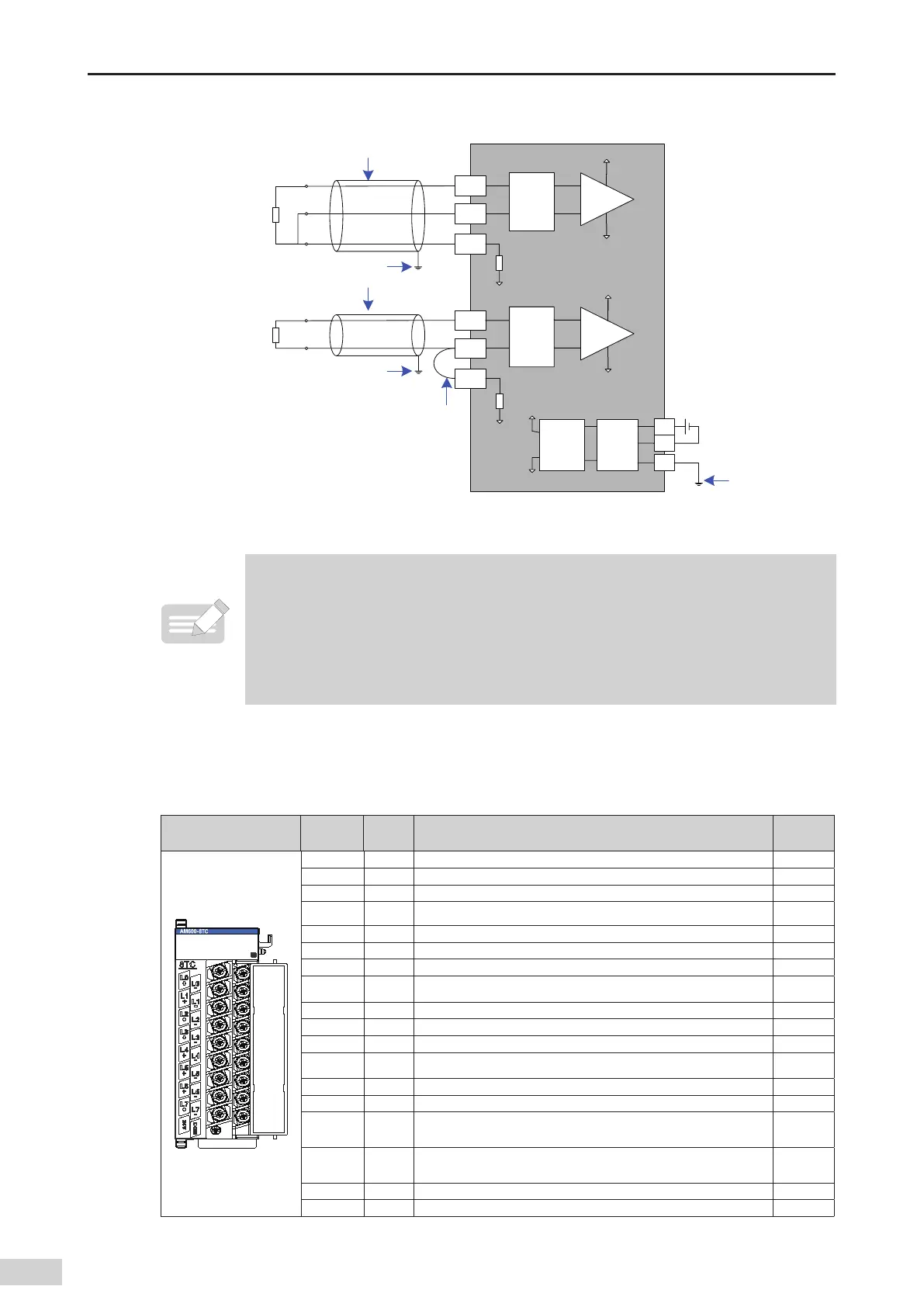
2) External wiring
C5XPXJSFT
B5ISFFXJSFT
琞
琞
琞
15
7
$0.
'(
'JMUFS
%$%$
DPOWFSUFS
'JMUFS
'JMUFS
*/"
*/#
*/C
*/"
*/#
*/C
"(/%
"(/%
"(/%
"(/%
"(/%
7
7
7
7
FYUFSOBM%$
QPXFS
琞
琞
15
琞
Figure 5-46 AM600-4PT module wiring
◆
*1 Use shielded cables;
◆
*2 If two-wire wiring is used
,
the INB and Inb channels need to be shorted
,
and the cable
resistance aects the measurement;
◆
*3 Use cables with small wire resistance and without resistance dierence between the three
wires;
◆
*4 The module should be mounted on a well-grounded metal bracket
,
and ensure that the metal
shrapnel at the bottom of the module is in good contact with the bracket.
2 Terminal signal denitions of the temperature module (AM600-8TC/AM600-4TC)
■
The following table describes the terminals of the AM600-8TC temperature module. The L4+/
L4- ~L7+/ L7- terminals of the AM600-4TC temperature module are reserved.
Terminal Arrangement
Terminal
Symbol
Type Function
Terminal
No.
L0+ Input Thermocouple of channel 0 1
L0- Input Thermocouple of channel 0 2
L1+ Input Thermocouple of channel 1 3
L1- Input Thermocouple of channel 1 4
L2+ Input Thermocouple of channel 2 5
L2- Input Thermocouple of channel 2 6
L3+ Input Thermocouple of channel 3 7
L3- Input Thermocouple of channel 3 8
L4+ Input Thermocouple of channel 4 9
L4- Input Thermocouple of channel 4 10
L5+ Input Thermocouple of channel 5 11
L5- Input Thermocouple of channel 5 12
L6+ Input Thermocouple of channel 6 13
L6- Input Thermocouple of channel 6 14
L7+ Input
Thermocouple of channel 7/external cold-side compensation
(for high-accuracy external cold-side compensation)
15
L7- Input
Thermocouple of channel 7/external cold-side compensation
(for high-accuracy external cold-side compensation)
16
+24V Power +24 V power supply 17
COM Power 24 V power ground 18
 Loading...


