-41-
Introduction
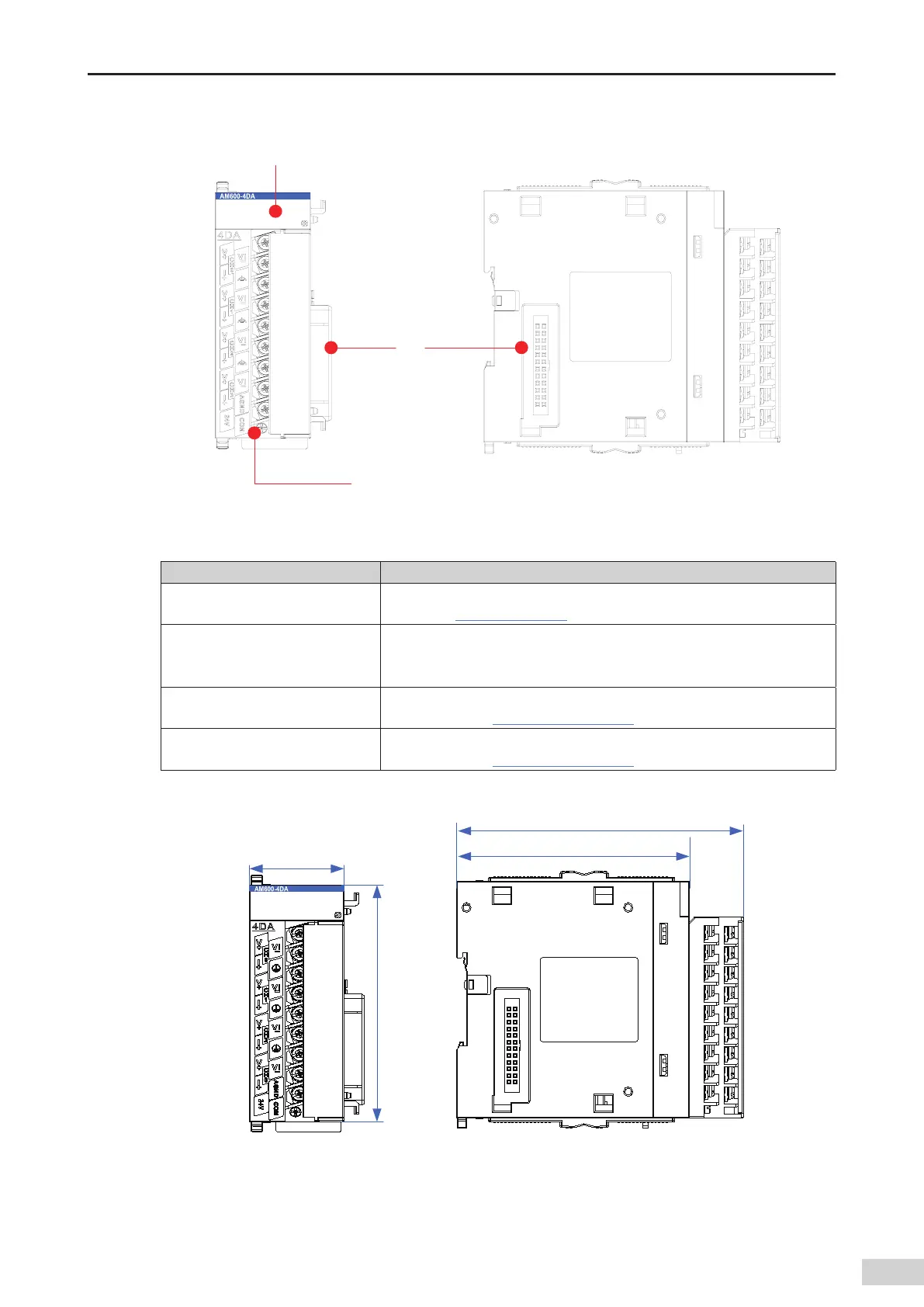
2) Module interface description
36/
&33
4JHOBMJOEJDBUPS
6TFSPVUQVU
UFSNJOBM
-PDBM
FYQBOTJPO
CBDLFOE
JOUFSGBDF
-PDBM
FYQBOTJPO
GSPOUFOE
JOUFSGBDF
Figure 3-19 Interfaces of the AO module
Interface Name Function
User output terminal
4-channel output (Voltage and current output supported. For details about
the use
,
see
"Chapter 5 Wiring"
.)
Signal indicators
RUN: operation state indicator
,
which is on during normal operation and o
when a fault occurs.
ERR: error state indicator
,
which is on when a fault occurs.
Local expansion module back-end
interface
Connects to the backward module and does not support hot swap. For details
about the use
,
see
"Chapter 4 Installation"
.
Local expansion module front-end
interface
Connects to the forward module and does not support hot swap. For details
about the use
,
see
"Chapter 4 Installation"
.
3) Dimensions (mm)
Figure 3-20 Dimensions of AO module
 Loading...


