-48-
Introduction
■
The following table lists the performance indicators:
Item Specications
Communication protocol EtherCAT
Service supported CoE (PDO
,
SDO) and FoE
Minimum synchronization period of 6-axis
cam
1250 μs (TYP)
Synchronization mode The servo uses a DC distributed clock. I/O uses I/O synchronization.
Physical layer 100BASE-TX
Baud rate 100 Mbit/s (100Base-TX)
Duplex mode Full duplex
Topological structure Linear topological structure
Transmission medium For the network cable
,
see the
"Chapter 5 Wiring"
.
Transmission distance Less than 100 M between two nodes
EtherCAT frame length 44 bytes to 1498 bytes
Process data A single Ethernet frame contains a maximum of 1486 bytes.
Synchronization jitter of two slaves < 1 μs
Refresh time
1000 digital inputs and outputs: approximately 30 μs; 32 servo axes:
approximately 100 μs
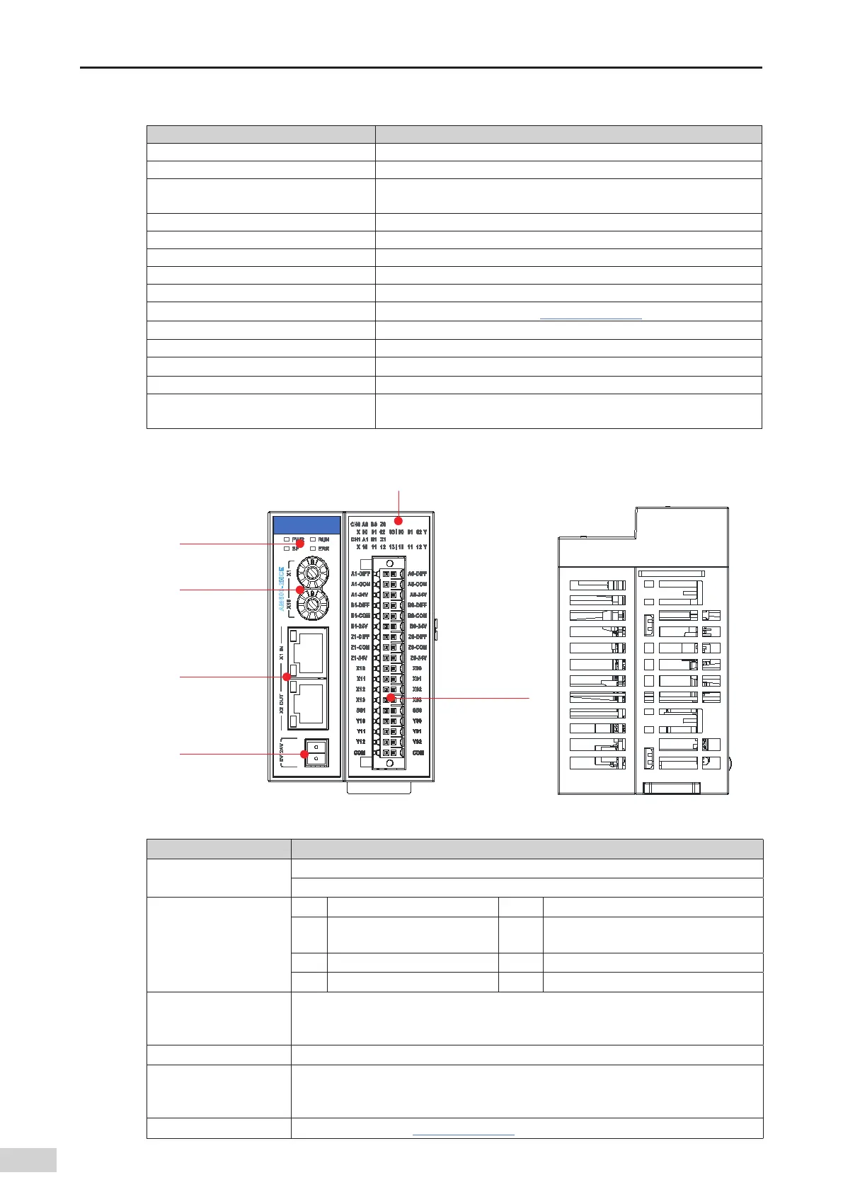
2) Module interface description
I/O signal indicator
EtherCAT
communication
port
Address switch
(rotary switch)
24 V power
input terminal
I/O terminal
Signal indicator
Figure 3-27 High-speped counting module interfaces
Interface Name Function
EtherCAT communication
port
X1 IN: EtherCAT input interface
X2 OUT: EtherCAT output port that connects to the back-end EtherCAT slave station
Signal indicators
PWR Power indicator Green On when the power is switched on
RUN Running indicator Green
On when the module is running
normally
SF Module fault indicator Red On when the module is faulty
ERR State machine error indicator Red On when a state machine error occurs
I/O signal indicator
I/O status indicator:
ON: I/O active
OFF: I/O inactive
24 V power input terminal Module power input
Address switch (rotary
switch)
Sets the slave station address: ADDR1/ADDR0: station address DIP switch. The address is
set in the hexadecimal format. Slave station decimal address = ADDR1 x 16 + ADDR0 x 1
(address range: 1 to 255)
User output terminal For the denition
,
see
"Chapter 5 Wiring"
.
 Loading...


