-50-
Introduction
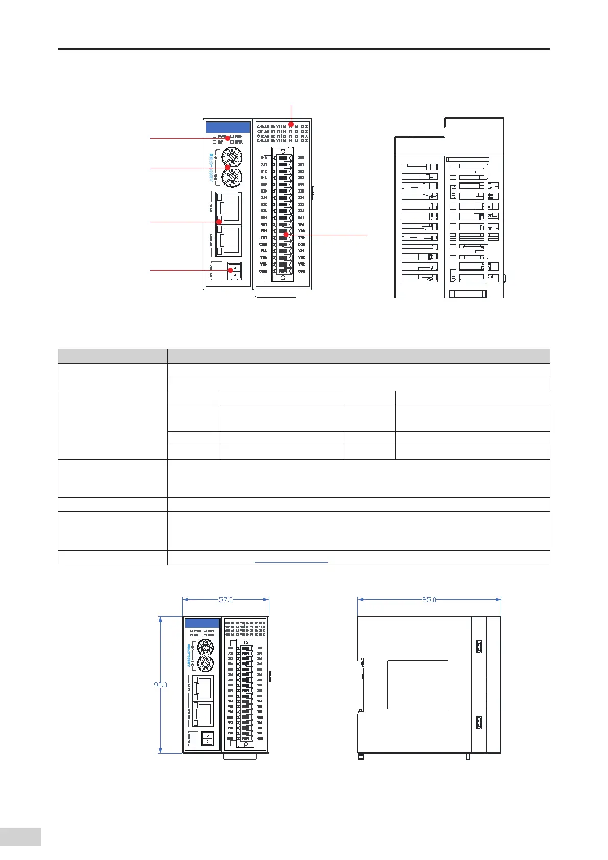
2) Module interface description
I/O signal indicator
EtherCAT
communication
port
Address switch
(rotary)
24 V power
input terminal
I/O terminal
Signal indicator
Figure 3-29 Positioning module interfaces
Interface Name Function
EtherCAT communication
port
X1 IN: EtherCAT input interface
X2 OUT: EtherCAT output interface that connects to the back-end EtherCAT slave station
Signal indicators
PWR Power indicator Green On when the power is switched on
RUN Running indicator Green
On when the module is running
normally
SF Module fault indicator Red On when the module is faulty
ERR State machine error indicator Red On when a state machine error occurs
I/O signal indicator
Corresponds to various I/O signals.
ON: I/O active
OFF: I/O inactive
24 V power input terminal Module power input
Address switch (rotary
switch)
Sets the slave station address: ADDR1/ADDR0: station address DIP switch. The address is set in the
hexadecimal format. Slave station decimal address = ADDR1 x 16 + ADDR0 x 1 (address range: 1 to
255)
User output terminal For the denition
,
see
"Chapter 5 Wiring"
.
3) AM600-4PME positioning module dimensions (mm)
 Loading...


